Transmission for a vehicle

a technology for transmission and vehicles, applied in the direction of mechanical actuated clutches, interlocking clutches, gearing, etc., can solve the problems of excessively large shock wave which an occupant can recognize and generate shock wave that gives an uncomfortable feeling/sensation to the occupant of the vehicle, and achieve the effect of reducing the torque change shock wav

Inactive Publication Date: 2016-01-14
AISIN AI CO LTD
View PDF4 Cites 1 Cited by
  • Summary
  • Abstract
  • Description
  • Claims
  • Application Information

AI Technical Summary

Benefits of technology

[0010]As described above, according to the present invention, it becomes possible to reduce the torque changed shock at the

Problems solved by technology

When the double engagement state occurs, an excessively large shock wave which an occupant can recognize is generated due to a collision between input side inertia an

Method used


Image

  • Transmission for a vehicle
  • Transmission for a vehicle
  • Transmission for a vehicle

Examples


Embodiment Construction

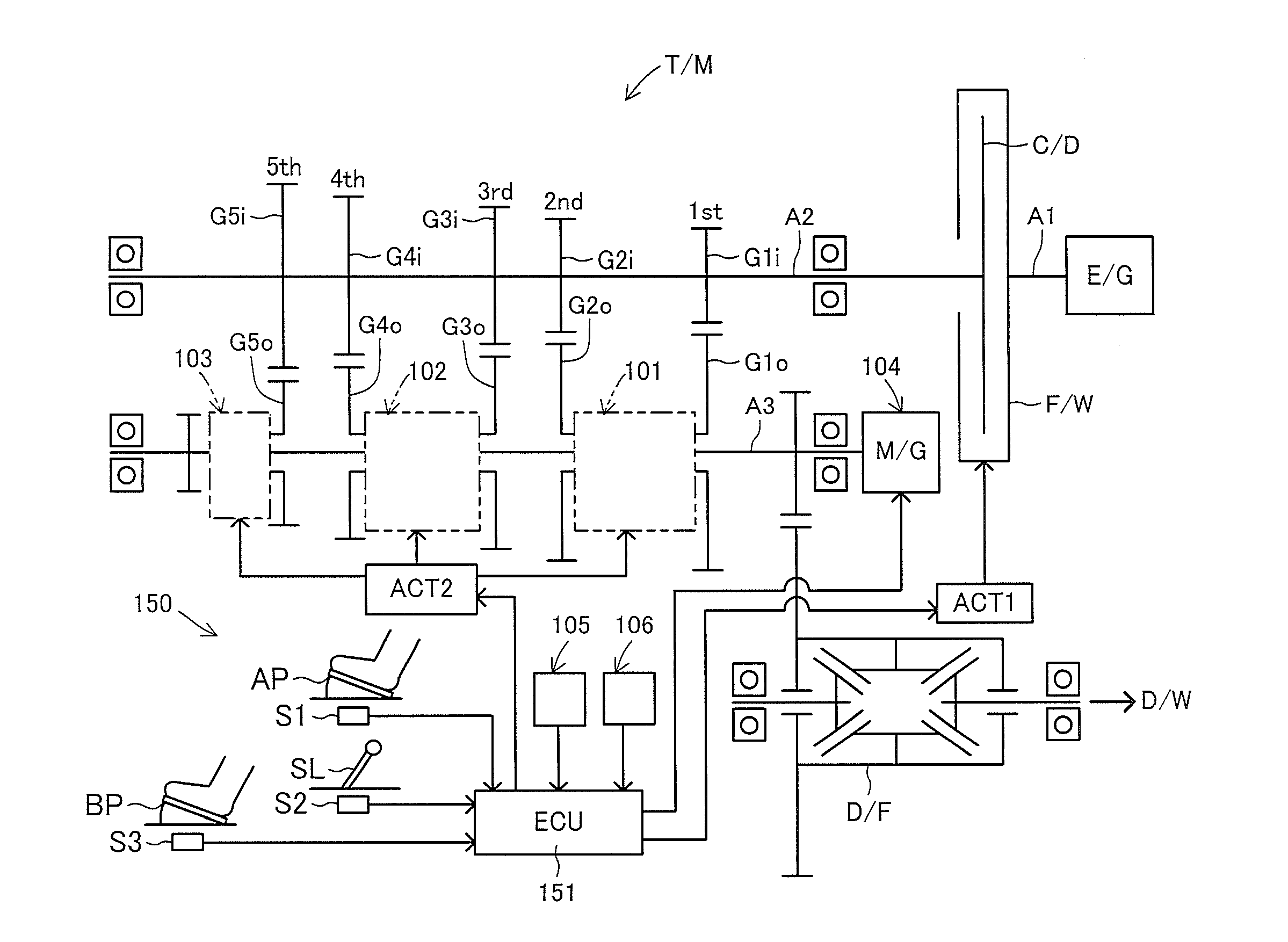
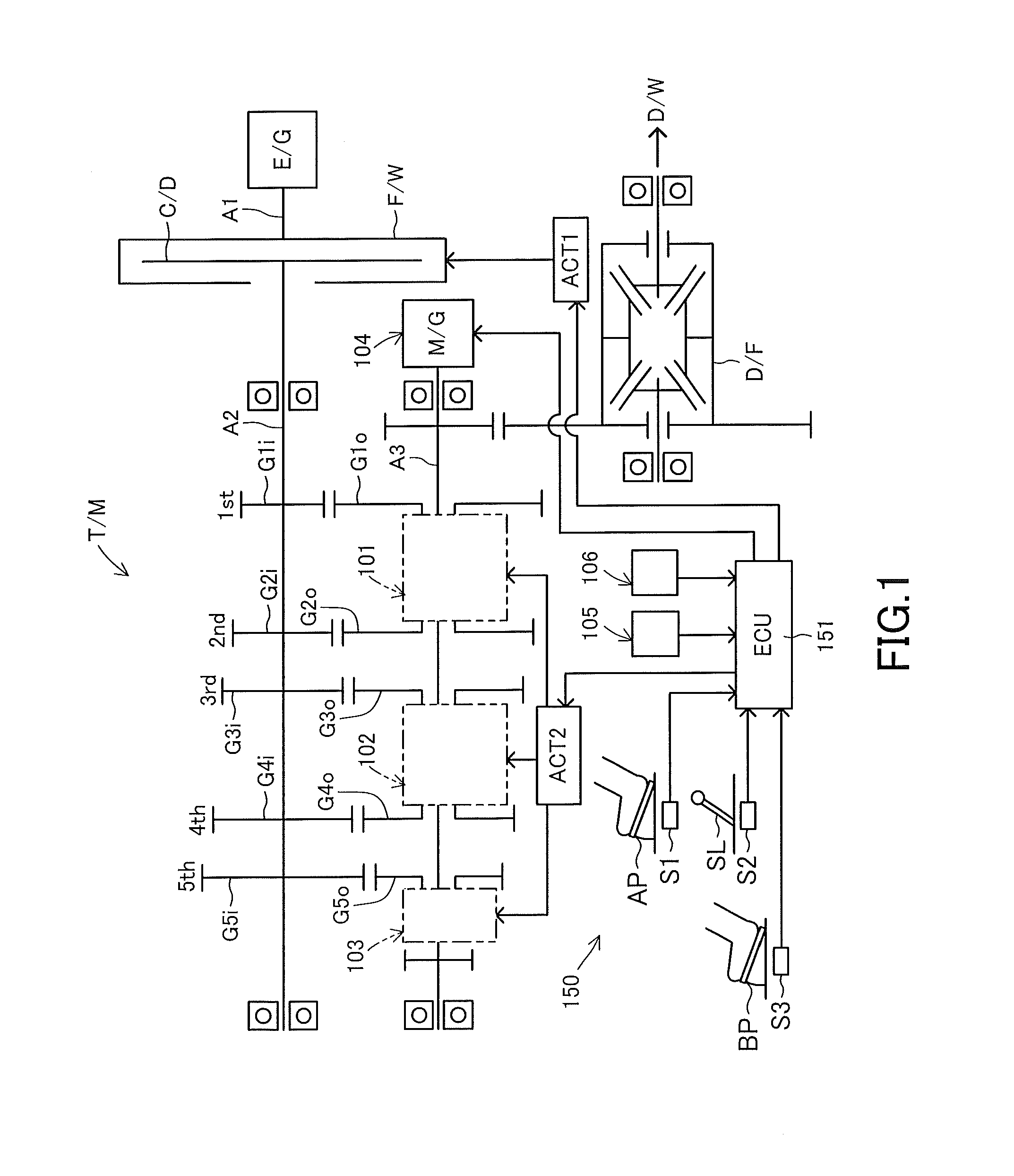
[0019]An embodiment of a transmission for a vehicle according to the present invention will be described hereinafter with reference to the accompanying drawings. The transmission T / M (for a vehicle) of the embodiment according to the present invention is interposed in a power transmission system connecting a drive output shaft of an engine serving as a driving source of the vehicle and the drive wheels of the vehicle. The transmission T / M is provided with five gear stages for driving the vehicle forward (first-speed driven gear (1 st)˜fifth-speed driven gear (5th)) and a single gear stage (reverse gear) for driving the vehicle backward.

[0020]As shown in FIG. 1, the transmission T / M comprises an input shaft A2 and an output shaft A3. The input shaft A2 of the transmission T / M is connected to a drive output shaft A1 of the engine E / G via a clutch C / D and a flywheel F / W. A power transmission system is formed between the input shaft A2 and the drive output shaft A1 of the engine E / G. Th...


PUM


Abstract

A power transmission mechanism transmits torque of the input shaft to the output shaft, and includes gear mechanisms corresponding to each of gear stages respectively. A control device controls the power transmission mechanism to realize one of a first control mode, a second control mode and a third control mode selectively. In the first control mode, a first gear stage is selected and the power transmission mechanism transmits torque via only a first gear mechanism. In the second control mode, a second gear stage is selected and the power transmission mechanism transmits torque via only a second gear mechanism. In the third control mode, at gear-shift from the first gear stage to the second gear stage, the power transmission mechanism circulates torque having a prescribed amount to the input shaft from the output shaft via the first gear mechanism while transmitting torque of the input shaft to the output shaft.

Description

TECHNICAL FIELD[0001]The present invention relates to a transmission for a vehicle.BACKGROUND ART[0002]An example of a transmission for a vehicle is disclosed in Japanese Unexamined Patent Application Publication (Translation of PCT Application) No. 2010-510464. One engaging member (an engagement element set) and the other engaging member (an engagement element set) are provided in this transmission. The one engaging member is engageable with a first engaged member (driving structure) which is provided on / for a low speed gear, while the other engaging member is engageable with a second engaged member (driving structure) which is provided on / for a high speed gear. Each of these two engaging members (engaging element sets) is configured to be driven independently in the axial direction by a drive member and an actuator which are dedicated for each of the engaging members. According to this configuration, it is possible to shift a gear position (or a speed gear stage) from a low speed ...

Claims


Application Information

Patent Timeline
IPC IPC(8): F16H3/12F16H3/089F16H61/04F16H61/682
CPCF16H3/126F16H3/089F16H2200/0047F16H61/682F16H2003/0807F16H61/04F16D11/10F16D11/14F16D21/02F16D23/06F16H61/684F16H63/502F16H2061/0474B60K2006/4808
Inventor MASUI, YUUKI
Owner AISIN AI CO LTD
Why Eureka
Try Eureka