
Heat source apparatus and method of starting the apparatus

a technology of heating source and apparatus, which is applied in the direction of mechanical equipment, refrigeration components, lighting and heating equipment, etc., can solve the problems of slow speed, difficulty in controlling, and slow speed of electronic expansion valve opening degree, and achieve rapid decrease of suction pressure and stable operation

Inactive Publication Date: 2007-03-22
HITACHI APPLIANCES INC
View PDF9 Cites 34 Cited by
  • Summary
  • Abstract
  • Description
  • Claims
  • Application Information

AI Technical Summary

Benefits of technology

[0014] It is an object of the invention to realize a heat source apparatus, which can control an opening degree of an electronic expansion valve and in which a stable operation can be reached in a short period of time after the heat source apparatus is started, without being accompanied by a rapid decrease in suction pressure.
[0017] A speed, at which the electronic expansion valve is driven, is made slow as approaching the predetermined discharge side super-heat, and time required from starting until a stable operation is shortened while avoiding a rapid decrease in pressure.
[0018] According to the invention, it is possible to realize a heat source apparatus, which can control an opening degree of an electronic expansion valve and in which a stable operation can be reached in a short period of time after the heat source apparatus is started, without being accompanied by a rapid decrease in suction pressure, and a method of starting the heat source apparatus.

Problems solved by technology

Hereupon, super-heat of a refrigerant sucked into the compressor assumes a relatively small value in the order of 3 to 5 K. Therefore, taking account of a detection error in the temperature detector, control of an opening degree of the electronic expansion valve involves a large error due to a detected temperature of the temperature detector, so that the compressor may be damaged due to liquid back.
In this case, a speed, at which an opening degree of the electronic expansion valve is decreased, is difficult to control since it is necessary to avoid freezing of water or brine in an evaporator, which is caused when pressure and temperature of a refrigerant rapidly decrease.
Consequently, it takes time in closing the electronic expansion valve until a unit operates stably.
Accordingly, it is feared that an operation is prolonged in a state, in which liquid back to a screw compressor is apt to occur, to cause shortage of an oil film on a rotor part in the screw compressor, and there is a possibility that damage is given to a screw rotor.
Hereupon, while it is conceivable to use the technology described in JP-A-2003-106610 to control an opening degree of an electronic expansion valve, correction of a detection error of a suction side super-heat can be achieved but it is difficult to realize shortening of an operating time from starting till a stable operation.
Therefore, since temperature is constant at a certain pressure, at what refrigerant dryness a refrigerant is sucked into a compressor is not understandable in a state, in which a compressor suction side refrigerant super-heat is negative (compressor suction gas temperature<saturation temperature at compressor suction pressure), that is, a state of liquid back, so that there is a fear that control becomes difficult such as rapidly excessive throttling of an opening degree of an expansion valve.

Method used


Image

  • Heat source apparatus and method of starting the apparatus
  • Heat source apparatus and method of starting the apparatus
  • Heat source apparatus and method of starting the apparatus

Examples


Embodiment Construction

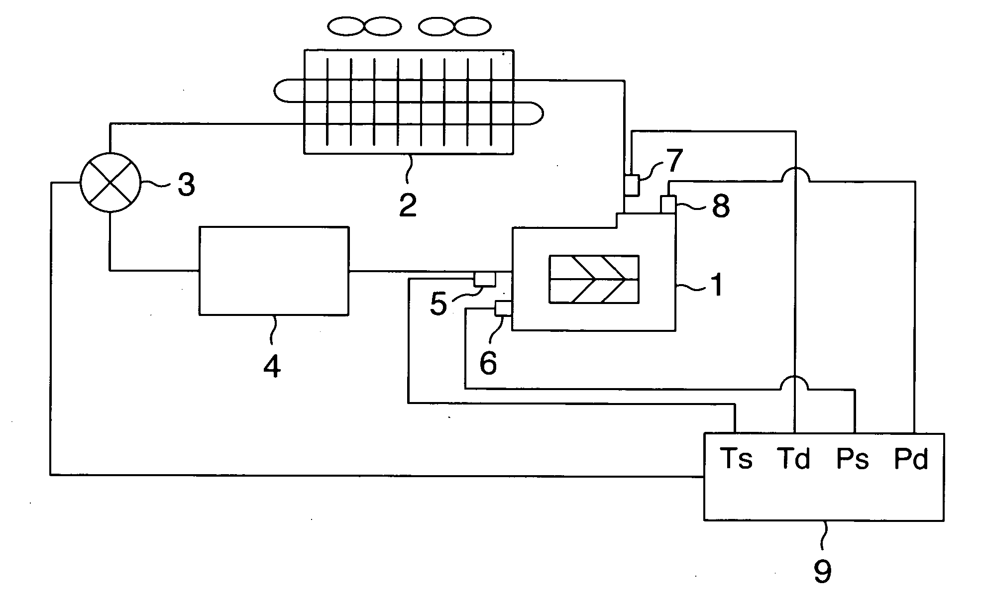
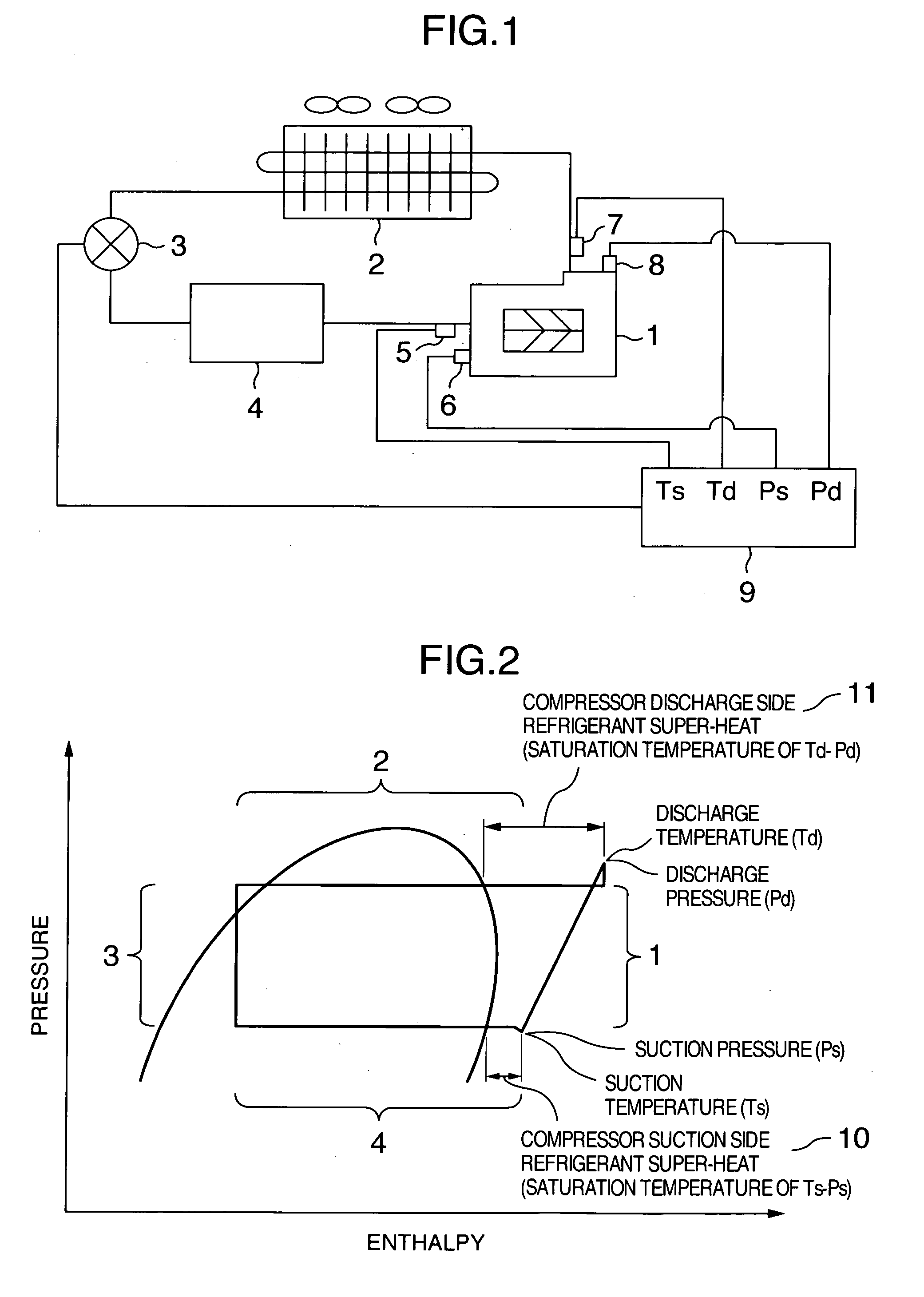
[0026]FIG. 1 is a view showing a schematic construction of an air-cooling type screw chiller unit which is a heat source apparatus, to which the invention is applied, and mainly showing a pipe line system diagram and component parts related to control of an electronic expansion valve.

[0027] In FIG. 1, a refrigerant system is formed by a screw compressor 1, an air side heat exchanger (condenser) 2, an electronic expansion valve 3 and a water side heat exchanger (evaporator) 4. Further, a control system is formed by a detector 5 for detecting temperature (Ts) of compressor suction gas, a detector 6 for detecting compressor suction pressure (Ps), a detector 7 for detecting temperature (Td) of compressor discharge gas, a detector 8 for detecting compressor discharge pressure (Pd), and an arithmetic processing part (opening degree control part) 9 that processes information from the detectors 5 to 8 to issue an opening degree command to the electronic expansion valve 3.

[0028] The arithm...


PUM


Abstract

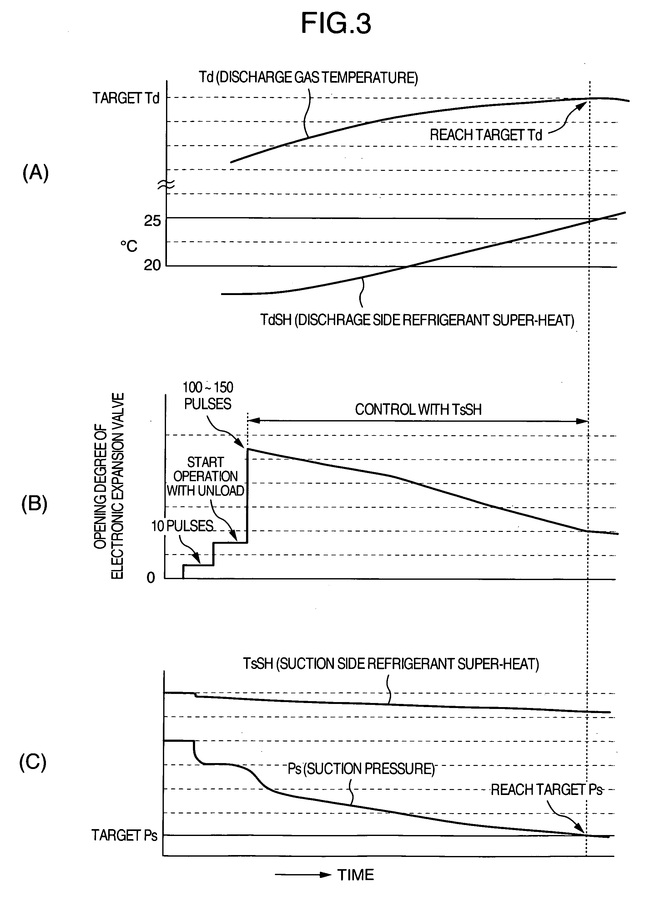
After a chiller unit is started, an opening command of 10 pulses is output to an electronic expansion valve, and after a predetermined period of time (at the time of starting with unload) elapses, an opening command of 100 to 150 pulses is output to open the electronic expansion valve up to a predetermined opening degree. Thereafter, a discharge side refrigerant super-heat TdSH is monitored and a closing command of 1 pulse / sec is output to the electronic expansion valve to drive the same in a closing direction in a short time until TdSH becomes 20 K. After TdSH has reached 20 K, a closing command of 1 pulse / 3 sec is output to the electronic expansion valve, until TdSH becomes 25 K, to drive the electronic expansion valve 3 at a smaller speed in the closing direction than that speed in the closing direction until TdSH becomes 20 K. After TdSH reaches 25 K, it is judged that an operation has shifted to a stable operation, and the opening degree of the electronic expansion valve is controlled while a suction side refrigerant super-heat TsSH is monitored.

Description

INCORPORATION BY REFERENCE [0001] The present application claims priority from Japanese application JP2005-273672 filed on Sep. 21, 2005, the content of which is hereby incorporated by reference into this application. BACKGROUND OF THE INVENTION [0002] The present invention relates to a water-cooled or air-cooled type heat source apparatus having a refrigerating cycle, in which an electronic expansion valve automatically adjusts an amount of a refrigerant flowing into an evaporator according to an operating state, and a method of starting the apparatus. [0003] In a refrigerating apparatus which is a heat source apparatus, a compressor, a condenser, an electronic expansion valve, and an evaporator are provided. [0004] A temperature detector detects super-heat of a refrigerant sucked into the compressor and an opening degree of the electronic expansion valve is controlled so that the detected super-heat falls in a predetermined range. [0005] Hereupon, super-heat of a refrigerant sucke...

Claims


Application Information

Patent Timeline
Patent Type & Authority Applications(United States)
IPC IPC(8): F25B41/04
CPCF25B41/062F25B2341/0652F25B2500/26F25B2600/026Y02B30/72F25B2700/1931F25B2700/1933F25B2700/21151F25B2700/21152F25B2600/2513Y02B30/70F25B41/347
Inventor AIYAMA, MASAYUKIKIKUCHI, SHOUJIISHIBANE, KYUUHEIISHIKI, YOSHIKAZUOKAMOTO, MITSUE
Owner HITACHI APPLIANCES INC
Learn More