
Hermetic compressor and manufacturing method of suction muffler

a manufacturing method and compressor technology, applied in the direction of positive displacement liquid engines, pumps, machines/engines, etc., can solve problems such as acoustic transmission loss, and achieve the effects of suppressing heat exchange, reducing noise, and further reducing sucking efficiency

Inactive Publication Date: 2007-03-15
PANASONIC CORP
View PDF21 Cites 9 Cited by
  • Summary
  • Abstract
  • Description
  • Claims
  • Application Information

AI Technical Summary

Benefits of technology

[0033] The present invention solves the above-mentioned conventional problems and has an object to provide the hermetic compressor in which the suck efficiency is high and the noise vibration is small, and the manufacturing method of the suction muffler.
[0034] In order to solve the above-mentioned conventional problems, in the hermetic compressor of the present invention, at least -a part of a casing of the suction muffler is foam-molded. Thus, due to the thermal insulating effect of bubbles generated within foamed synthetic resin, this has an action of extremely improving the thermal insulating performance under the same volume, and dropping the loss caused by heat reception, as compared with non-foamed resin, and also has an action of increasing the acoustic transmission loss because acoustic energy is absorbed by the friction between the gas within the bubble and the synthetic resin material around the bubble.
[0035] The hermetic compressor of the present invention can make the suck efficiency of the refrigerant gas higher and reduce the noise vibration.

Problems solved by technology

Moreover, the absorption of the acoustic energy caused by the friction between the gas within the bubble and the material around the bubble increases the acoustic transmission loss, which enables the reduction in the noise vibration.

Method used


Image

  • Hermetic compressor and manufacturing method of suction muffler
  • Hermetic compressor and manufacturing method of suction muffler
  • Hermetic compressor and manufacturing method of suction muffler

Examples


first embodiment

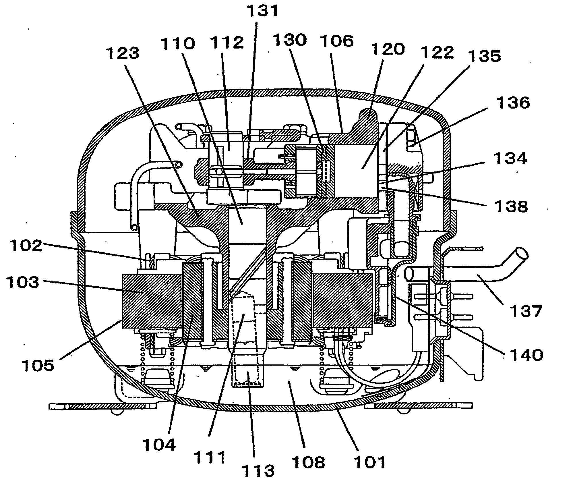
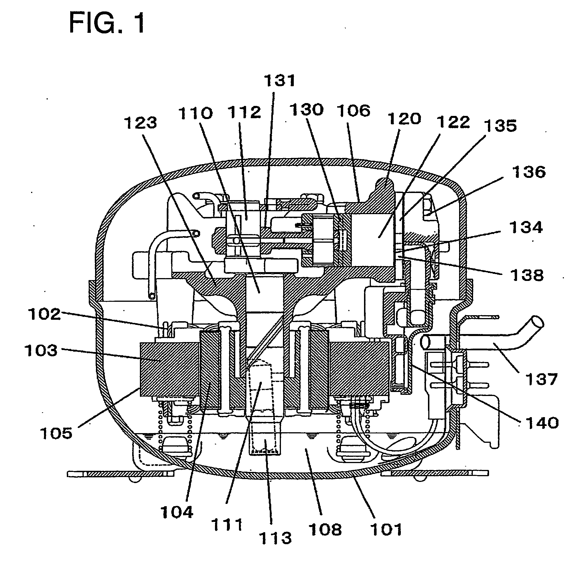
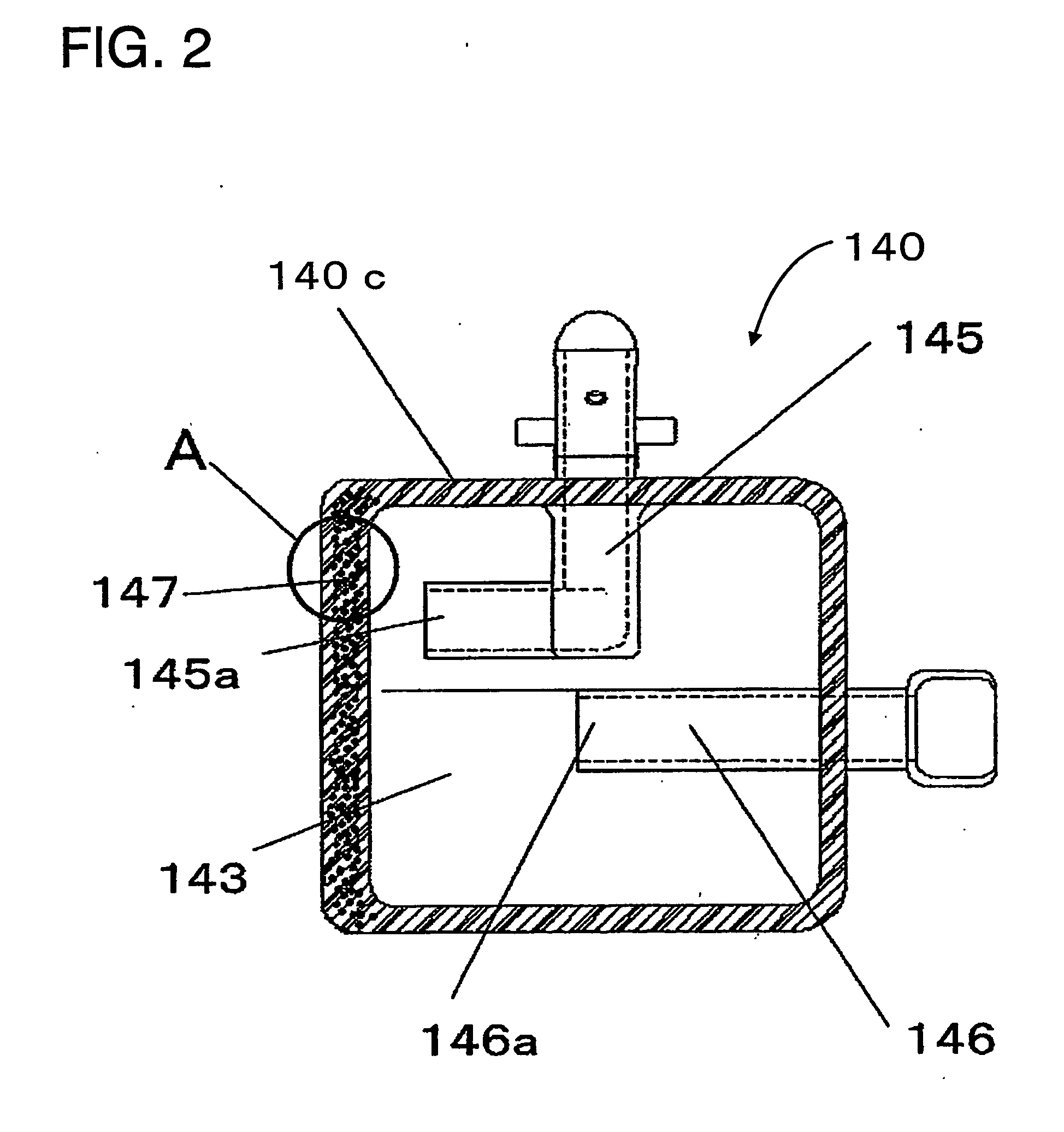
[0084]FIG. 1 is a sectional view of a hermetic compressor in the first embodiment of the present invention, and FIG. 2 is a sectional view of a suction muffler of the hermetic compressor in the same embodiment. FIG. 3 is an enlarged sectional view of a wall A-portion in FIG. 2. FIG. 4 is a main portion sectional view of a corner in the suction muffler in the same embodiment. FIGS. 5A to 5C are schematic configuration views of a foam molding machine in the same embodiment. FIG. 6 is a front view showing a suction muffler body and a runner in the same embodiment.

[0085] In FIG. 1, a hermetic vessel 101 accommodates: a motor element 105 composed of a rotator 104 and a stator 103 holding a coil portion 102; and a compression element 106 driven by the motor element 105. A lubricating oil 108 is stored in the hermetic vessel 101. By the way, as refrigerant gas (not shown), R600a of natural refrigerant is used.

[0086] Also, the motor element 105 is driven by an inverter method including a ...

second embodiment

[0122]FIG. 7 is a sectional view of a suction muffler of a hermetic compressor in the second embodiment of the present invention, and FIG. 8 is an enlarged view of a foaming portion of the suction muffler in the same embodiment. FIG. 9 is a rear view of a suction muffler body in the same embodiment, FIG. 10 is a decomposed perspective view of the suction muffler of the hermetic compressor in the same embodiment, and FIG. 11 is an enlarged view of a bonding section between a cover and the suction muffler body in the same embodiment. FIGS. 12A to 12C are schematic configuration views of a supercritical foam molding machine in the same embodiment. By the way, the configuration of the hermetic compressor in this embodiment is the same configuration as the first embodiment except the suction muffler. Thus, the explanation is omitted.

[0123] As shown in FIG. 7, the suction muffler 240 has a casing 240C composed of a plurality of walls, a first linkage path 245 and a second linkage path 24...

third embodiment

[0143]FIG. 13 is a sectional view of a hermetic compressor in the third embodiment of the present invention, and FIG. 14 is a decomposition view of a suction muffler in the same embodiment. FIGS. 15A to 15C are schematic configuration views of a supercritical foam molding machine in the same embodiment. By the way, the configuration of the hermetic compressor in this embodiment is the same configuration as the second embodiment, except the suction muffler. Thus, the explanation is omitted.

[0144] A suction muffler 340 is composed of three parts of a motor element side 341, an anti-motor element side 342 and a center 343. Most of the portions of their elements constitute a casing 340C. The suction muffler 340 where the three parts of the motor element side 341, the anti-motor element side 342 and the center 343 are combined has a first linkage path 345 and a second linkage path 346, and a sound attenuation space 347 is formed inside the casing 340C. Also, the first linkage path 345 i...


PUM

PropertyMeasurementUnit
diameteraaaaaaaaaa
frequencyaaaaaaaaaa
thicknessaaaaaaaaaa

Abstract

This relates to a hermetic compressor and a manufacturing method of a suction muffler, and discloses a technique for making energy efficiency higher and reducing noise. According to that technique, in a suction muffler 140 having a sound attenuation space 143, by foam-molding a wall 147, such as an opposite surface and the like, where open ends 145a, 146a within the sound attenuation space among the walls constituting a casing 140C of the suction muffler 140 are opened, it is possible to reduce the heating action of refrigerant gas released into the sound attenuation space 143 effectively in a space-saving manner, and make a sucking efficiency higher, and effectively absorb a refrigerant pulsation tone radiated in the open end 145a within the sound attenuation space, and consequently reduce the noise.

Description

TECHNICAL FIELD [0001] The present invention relates to a hermetic compressor for use in a refrigerator, an air conditioner, a freezing refrigerating apparatus or the like, and more particularly relates to its suction muffler and an improvement of its manufacturing method. BACKGROUND ART [0002] In recent years, a hermetic compressor used in a freezing refrigerating apparatus or the like strongly desires that energy efficiency is high, in addition to a fact that the noise caused by an operation is low. [0003] As a conventional hermetic compressor, there is a hermetic compressor whose energy efficiency is improved by improving the sound attenuation effect of a suction muffler and effectively using the sound attenuation effect and consequently increasing the refrigerant circulation quantity into a compression chamber (for example, refer to the following patent document 1). [0004] Also, there is a hermetic compressor whose energy efficiency is improved by maintaining the refrigerant gas...

Claims


Application Information

Patent Timeline
Patent Type & Authority Applications(United States)
IPC IPC(8): F04B35/04F04B39/00
CPCF04B39/0072B29C44/348C08G2101/00F04B35/04F04B39/0061F04B39/023F04B39/121F05B2210/14F05B2280/6012F05B2280/6015Y10S417/902
Inventor NAKANO, AKIRAINAGAKI, KO
Owner PANASONIC CORP
Learn More