
Image fixing apparatus and image forming apparatus capable of effectively controlling an image fixing temperature

Inactive Publication Date: 2007-03-15
RICOH KK
View PDF2 Cites 39 Cited by
  • Summary
  • Abstract
  • Description
  • Claims
  • Application Information

AI Technical Summary

Benefits of technology

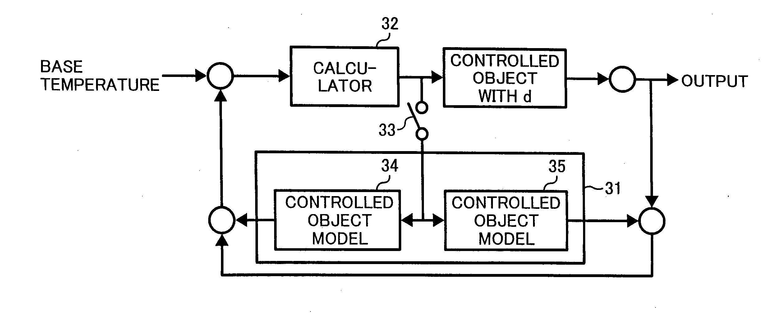
[0014] The present invention provides a novel image fixing apparatus that controls temperature of a rotating member for fixing with compensation for delay by using a Smith predictor with a controlled object model to reduce temperature ripple effectively. In one example, the image fixing apparatus includes a pair of rotating members to form a nip region, a heater to heat the rotating member, a temperature sensor to detect temperature of the rotating

Problems solved by technology

If the temperature is higher or lower than the target, a poor image, referred to as an offset image, may be formed or poor fixing may occur.
The above techniques, however, require a high accuracy in controlling temperature of the fixing member due to its low heat capacity.
Although the ON-OFF controlling is used in this method, carrying out precise temperature control may be difficult due to a temperature ripple.
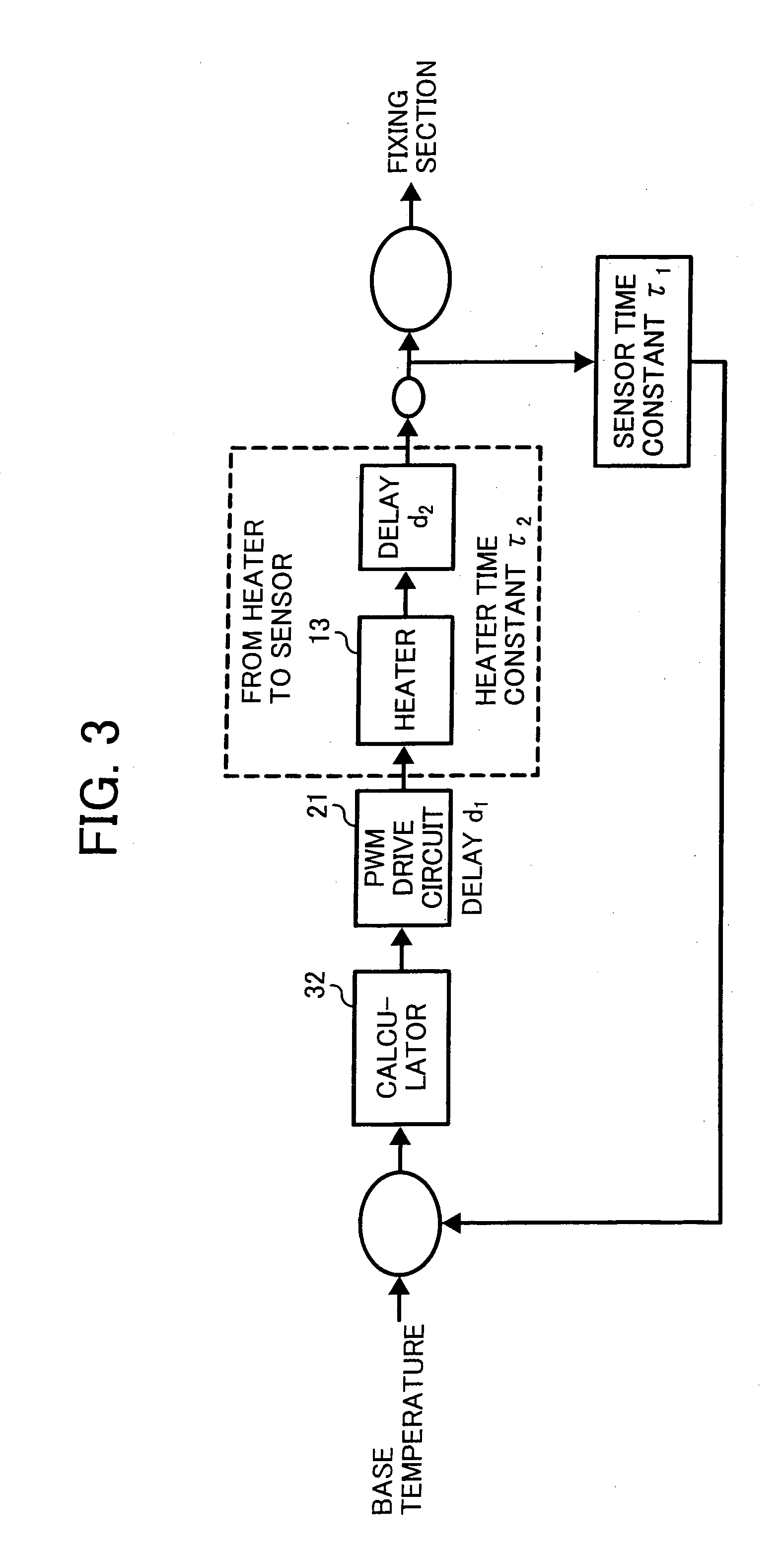
Even if the control method with the compensation is used, an exothermic delay in the heater, a heat transmission delay from the heater to a fixing member surface, a detecting delay from a slow response of a temperature sensor, and a delay from a heater driver to the temperature sensor may occur.
They may cause a temperature ripple.
Furthermore, the temperature ripple may easily occur in a belt fixing apparatus, because the heat delay in the belt is greater.

Method used


Image

  • Image fixing apparatus and image forming apparatus capable of effectively controlling an image fixing temperature
  • Image fixing apparatus and image forming apparatus capable of effectively controlling an image fixing temperature
  • Image fixing apparatus and image forming apparatus capable of effectively controlling an image fixing temperature

Examples


Embodiment Construction

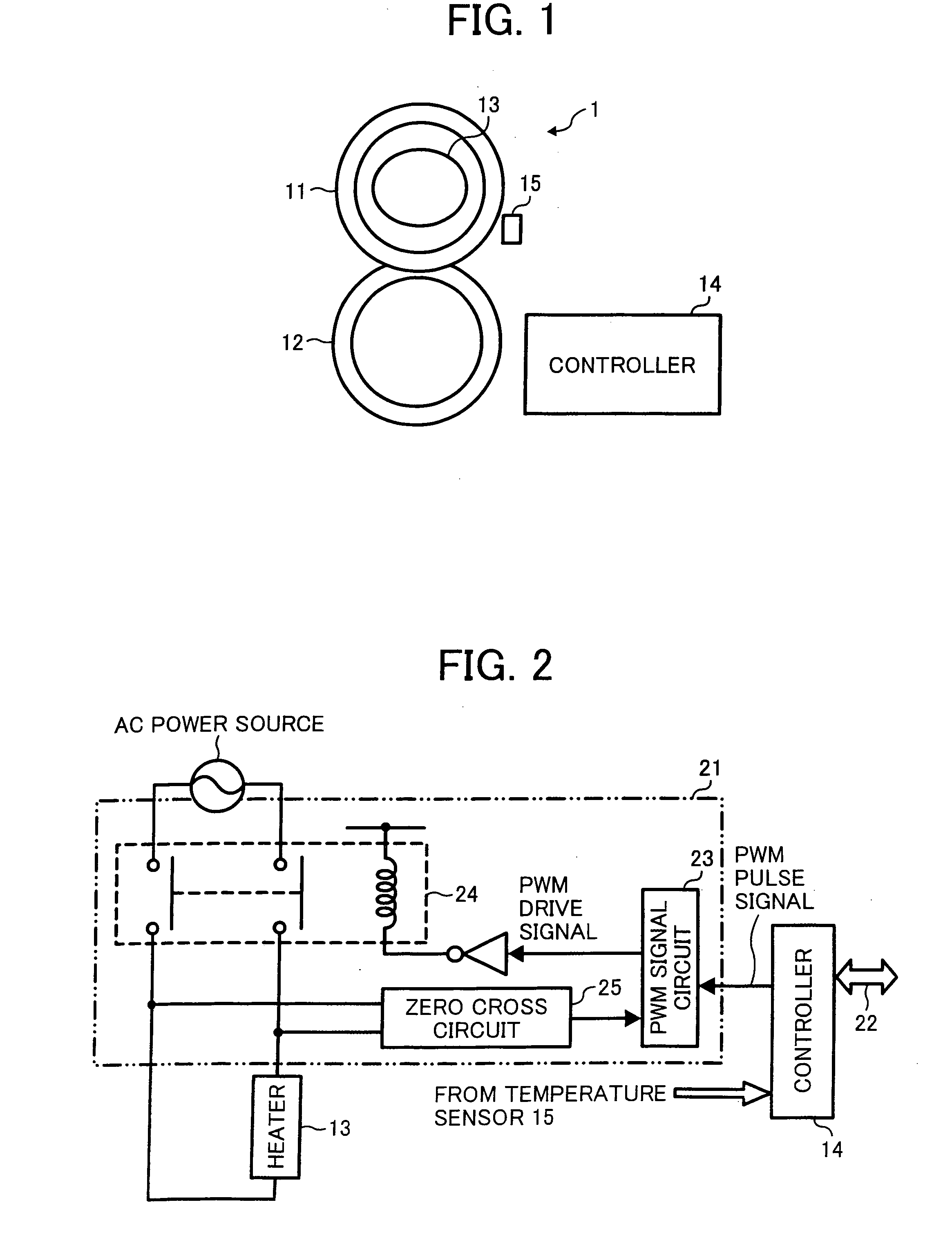
[0030] In describing preferred embodiments illustrated in the drawings, specific terminology is employed for the sake of clarity. However, the disclosure of this patent specification is not intended to be limited to the specific terminology so selected and it is to be understood that each specific element includes all technical equivalents that operate in a similar manner. Referring now to the drawings, wherein like reference numerals designate identical or corresponding parts throughout the several views, particularly to FIG. 1, an image fixing apparatus 1 according to an exemplary embodiment of the present invention is explained.

[0031] The image fixing apparatus 1 of FIG. 1 is for use in an electrophotographic image forming apparatus such as a laser printer, a digital copier, a facsimile machine, a printer-fax-copy multifunction machine, etc. This image fixing apparatus 1 uses a roller fixing system. As illustrated in FIG. 1, the fixing apparatus 1 includes rotating members 11 an...


PUM


Abstract

An image fixing apparatus controls temperature of a rotating member for fixing with compensation for delay by using a Smith predictor with a controlled object model to reduce temperature ripple effectively. In one example, the image fixing apparatus includes a pair of rotating members to form a nip portion, a heater to heat the rotating member, a temperature sensor to detect temperature of the rotating member, a calculator to calculate a heat value to attain a target temperature of the rotating member, a controller to control the heater based on a calculation result of the heat value with compensation for delay using a model according to the calculation result, and a selector to select a control in which an output of the compensation is input into the calculator or a control in which the output of the compensation is not input into the calculator.

Description

BACKGROUND OF THE INVENTION [0001] 1. Field of the Invention [0002] The present invention generally relates to an image fixing apparatus and an image forming apparatus equipped with the fixing apparatus, and more particularly to an image fixing apparatus capable of fixing a toner image onto a recording medium by effectively controlling an image fixing temperature in an electrophotographic process. [0003] 2. Discussion of the Background [0004] A background image forming apparatus such as a printer, a copying machine, and a facsimile using an electrophotographic method is generally provided with an image fixing apparatus that melts and fixes a toner image onto a recording medium with heat. This heating type image fixing apparatus commonly includes a heater, a fixing member, and a rotating member. The heater is energized with power to produce heat. The fixing member is heated up to a target temperature by the heater. The rotating member is arranged in contact with the fixing member to ...

Claims


Application Information

Patent Timeline
IPC IPC(8): G03G15/20
CPCG03G15/2039
Inventor SEO, HIROSHIOGAWA, TADASHIYASUI, MOTOKAZUKOIDE, HIROSHI
Owner RICOH KK
Learn More