
Quick release bicycle wheel

a bicycle wheel and quick release technology, applied in the field of wheeled vehicles, can solve the problems of bicycles being extremely dangerous, the adjusting nut remains unscrewed, and the quick release cam does not produce enough, and achieves the effect of light weight and inexpensive manufacturing

Inactive Publication Date: 2007-03-08
MONTAGUE DAVID
View PDF25 Cites 22 Cited by
  • Summary
  • Abstract
  • Description
  • Claims
  • Application Information

AI Technical Summary

Benefits of technology

[0017] The objective of the present invention is to provide a wheel release system that is fool-proof, safe, and easy and intuitive to use by the inexperienced rider with no instructions. In addition, the system must be light weight, simple, and inexpensive to manufacture.
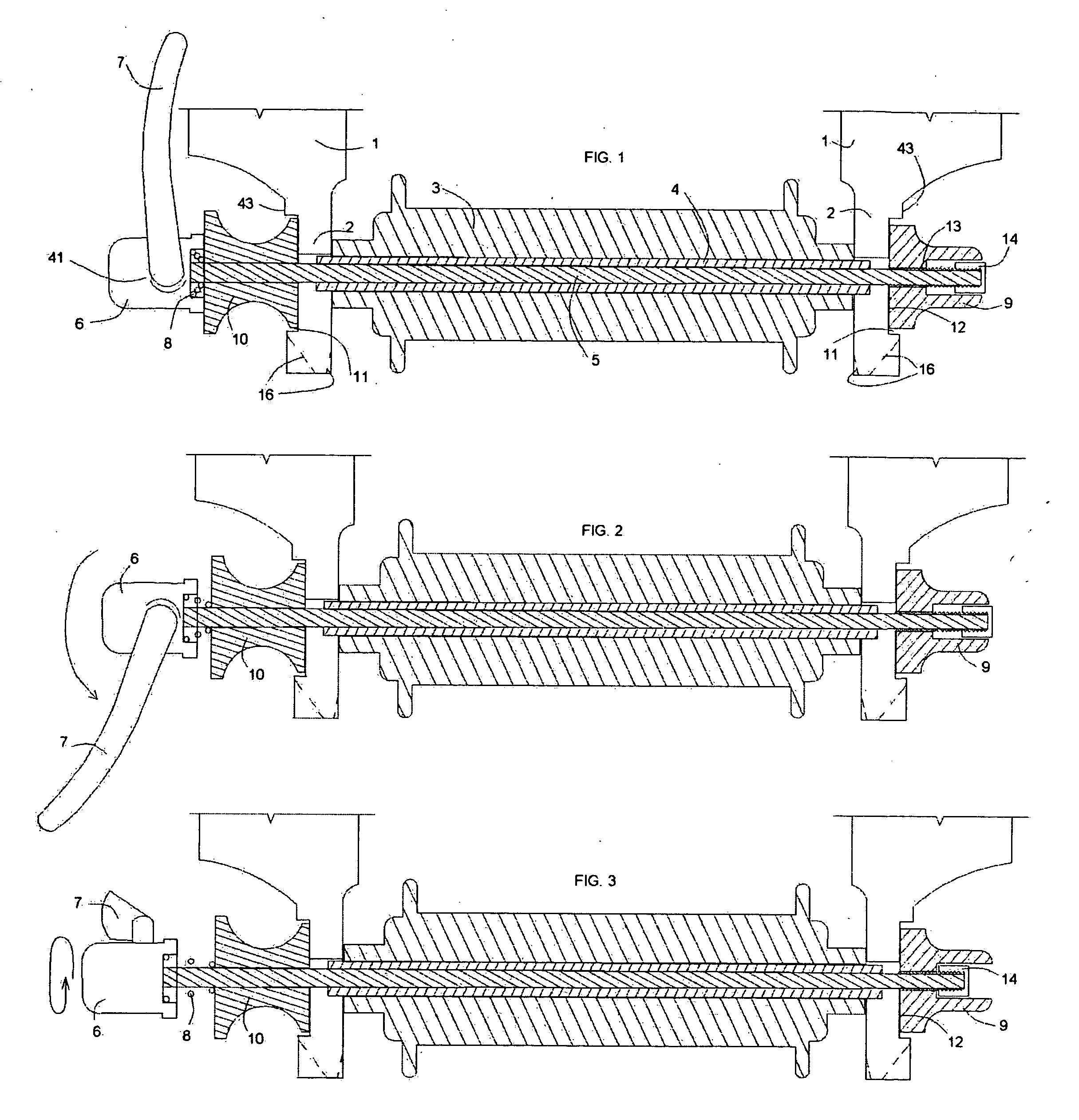
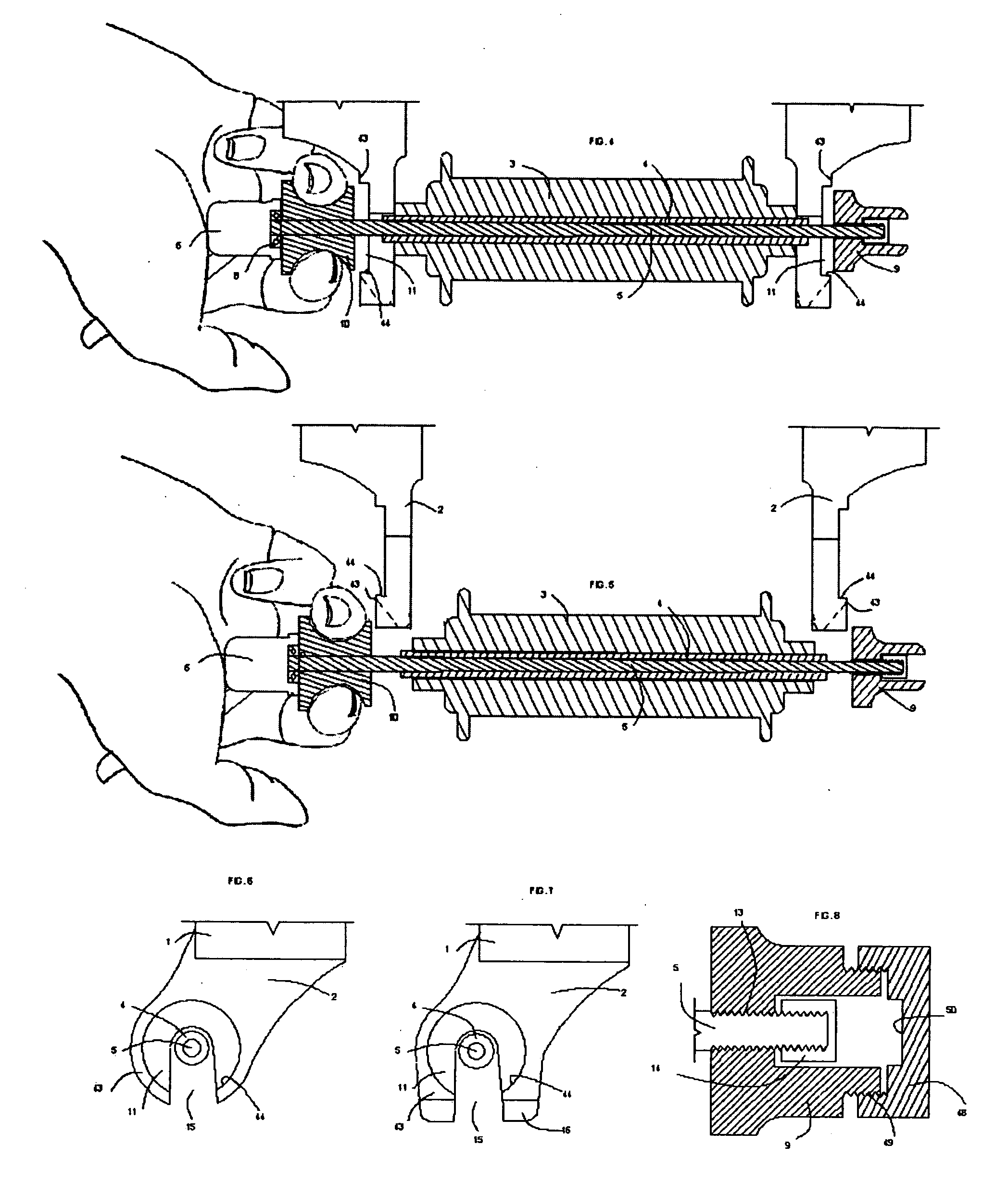
[0018] This objective is achieved in a system wherein the wheel can be easily removed by a manual operation on one side of the wheel but is prevented from unexpected separation at all times while engaged with the wheel. A laterally moving skewer mounted concentrically inside a hollow axle is equipped with a “non-touch” nut on one end and is spring loaded toward a quick release cam on the other end wherein in order to remove the wheel, the quick release cam is operated and in some cases the cam is then spun to loosen the adjusting nut, then the cam side assembly is squeezed and / or pushed axially inward and held in this position while the wheel is removed from the fork dropouts. When the wheel is again inserted into the wheel fork, the skewer automatically locks onto the dropouts, and subsequently if the quick release cam is inadvertently left open by the user, the wheel will be somewhat loose but will remain safely inserted in the wheel mounts. In this way, if the bicycle or wheeled vehicle looks safe to ride, it is safe to ride.

Problems solved by technology

The single process of opening the quick release cam does not produce enough “throw” to allow the quick release and the nut to clear the recess or tabs to exit from the dropout.
However, when the wheel is re-inserted into the dropouts, the adjusting nut remains unscrewed and the wheel, while looking like it is attached to the bicycle or other wheeled vehicle, is not.
In this “dangerous state” condition the bicycle is extremely dangerous as it appears to be rideable, but the front wheel can easily separate from the wheel fork.
In addition, in order to do this, the rider must hold the bicycle up with one hand, hold the quick release on one side of the bicycle with another hand, and turn the adjusting nut on the opposite side of the bicycle with yet another hand—making the process of safely fastening a wheel difficult at best for the average rider with only two hands.
Furthermore, the process of adjusting the nut to the correct tension such that the quick release cam operates properly is found to be challenging by many riders.
Several attempts have been made to solve some of these problems, however, none have yielded a satisfactory solution to both avoiding the “dangerous state” as well as making the process easy with only two hands.
However, in order to install the wheel on the bicycle, the operator must hold the bicycle with one hand, hold the quick release lever engaged with another hand, and insert the wheel with a third hand which could prove to be difficult for the average rider.
However, this device does not avoid the “dangerous state” condition, nor does it prevent the nut from being loosened too far and falling off the skewer.
This system also does not avoid the “dangerous state” wherein the wheel could appear to be mounted to the wheel fork for riding however the wheel is not secured.
None have provided both ease of use and absolute safety.

Method used


Image

  • Quick release bicycle wheel
  • Quick release bicycle wheel
  • Quick release bicycle wheel

Examples


Embodiment Construction

[0135] The following is a detailed description of the preferred embodiments of the present invention. It is apparent to those skilled in the art that any number of modifications can be made to the present invention and any such modification shall fall within the present invention even if not specifically shown.

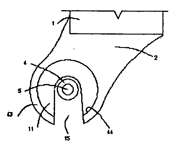
[0136] The fundamental underlying principle of the present invention comprises a wheel fork or vehicle frame with two wheel mounts, or dropouts, where each of the dropouts has a recessed surface or retaining tabs, either on its outer face, or its inner face, or both. The quick release wheel has a hollow axle hub and an interior mounted skewer, wherein said skewer has a quick release cam or other fastening device on one end and a nut on the other end and is spring loaded toward the quick release end such that the nut is always urged against and into the adjacent dropout recessed surface to prevent its rotation and exit from the recess. On the quick release end of the skewer, a...


PUM


Abstract

A wheel quick release system for a bicycle or other wheeled vehicle where the wheel can be easily removed by a manual operation on only one side of the wheel hub but is prevented from unexpected separation at all times while engaged with the wheel. A laterally moving skewer mounted concentrically inside a hollow axle is equipped with a “non-touch” nut on one end and is spring loaded toward a quick release cam on the other end thereby always urging the nut against the adjacent dropout. To remove the wheel, the quick release cam is operated and the quick release side assembly is pushed axially inward and a safety mechanism is operated and held in this position while the wheel is removed from the fork dropouts. When the wheel is again inserted into the wheel fork, the skewer automatically locks onto the dropouts, and subsequently if the quick release cam is inadvertently left open by the user, the wheel will be somewhat loose but will remain safely inserted in the wheel mounts. In this way, if the bicycle or wheeled vehicle looks safe to ride, it is safe to ride.

Description

[0001] This application is a Continuation-in-part of U.S. patent application Ser. No. 11 / 219,652 filed, Sep. 7, 2005 and titled “Quick Release Bicycle Wheel”.BACKGROUND OF THE INVENTION [0002] 1. Field of the Invention [0003] This invention relates in general to wheeled vehicles such as bicycles. In particular, this invention relates to an apparatus and the method of attaching a hollow axle wheel to a wheel mount wherein the wheel can be removed easily without the use of tools by operations on only one side of the wheel hub but will not unexpectedly separate from the wheel mounts. [0004] 2. Description of Prior Art [0005] Most better-quality bicycles on the market are equipped with quick release front (and sometimes rear) wheels. These bicycles use a standard method of avoiding unwanted separation of the front wheel comprising a recessed wheel mount. (or dropout), or small tabs which retains the wheel skewer at both ends, and thus the wheel, even when the quick release cam has been ...

Claims


Application Information

Patent Timeline
IPC IPC(8): B60B35/00
CPCB62K2206/00B62K25/02B60B27/026
Inventor MONTAGUE, DAVIDMONTAGUE, HARRY
Owner MONTAGUE DAVID
Learn More