Cap with visible tamper-indicating seal

a technology of sealing cap and visible tampering, applied in the field of sealing device, can solve the problems of difficult reattachment of the sealing cap to the bottle opening, limited combinations, and more expensive to manufacture caps in an array of colors, and achieve the effect of convenient customization

Inactive Publication Date: 2007-03-08
BLACKHAWK MOLDING
View PDF24 Cites 28 Cited by
  • Summary
  • Abstract
  • Description
  • Claims
  • Application Information

AI Technical Summary

Benefits of technology

[0009] The present inventions relate to a clear cap and liner combination for bottles which solves the problems of the prior art. The preferred cap of the present inventions is at least partially transparent or translucent to allow a customer to perceive the liner through the cap at the point of purchase. In one embodiment, the liner serves as a label, wherein the customer can perceive, through the cap, information such as printing. The printing can be indicative of the product, such as the name of the manufacturer, the name of the bottle contents, ingredients, and / or nutritional data. Because the liner can be easily customized to identify the product contained in a bottle, only one version of a cap need be manufactured for use with many different products. In a second embodiment, the liner serves as a tamper evident seal, wherein the customer can perceive, through the cap, whether the seal has been breached. As such, the consumer will know, at the point of purchase, whether or not the product has been tampered with. In a third embodiment, the liner serves as both a label and a seal, wherein the liner creates a liquid resistant seal between the cap and the opening of the bottle. In a forth embodiment, the liner serves as both a label and a tamper evident seal.
[0010] Also disclosed herein is a cap feature for reducing the surface friction of the cap to improve the efficiency of capping operations and / or for preventing damage to the transparent portion of the cap. The preferred cap feature comprises a raised portion on a top surface of the cap. The raised portion is preferably characterized as a circumferential ridge which is disposed adjacent to a perimeter of the lid of the cap. When inverted and laid on a flat surface, the cap is supported entirely by the raised portion. Consequently, the contact surface area is reduced as compared to a traditional cap. This reduces surface friction of the cap and improves feeding of the cap during capping operations. When the raised portion is embodied in a “clear” cap of the present invention, the raised portion has the characteristic of protecting the clear portion of the cap, minimizing distortion.
[0011] Although not limited as such, the preferred application for the present inventions is as a closure device for blow-molded bottles. There are two types of caps which are generally in use today with blow-molded bottles: push-on caps and screw-on caps. These kinds of caps are often injection molded with polyethylene (both high and low density) or polypropylene, a common material used in injection molding. To increase clarity of the cap, polishing of mold surfaces is important as is reducing the thickness of the top wall; however, the top wall should have a thickness greater than 0.025″. It is contemplated that the mold surfaces corresponding to both the top and bottom surface of the circular cover can be polished to increase clarity.

Problems solved by technology

The heat sealed liners are tamper evident in that, once the liner is removed from the lip of the bottle opening, the liner cannot be easily reattached to the bottle opening.
While the combination of bottle caps and liners of the types currently in use provides for an acceptable means of product identification and sealing, these combinations do have their limitations.
First, it is more costly to manufacture caps in an array of colors.
Second, the opaque caps of the prior art prevent consumers from ascertaining at the point of purchase whether the second level of tamper evidence—i.e. the heat seal label—has been tampered with.
In the event that the consumer finds a broken seal, it will be very inconvenient for the consumer to return the product to the store.

Method used


Image

  • Cap with visible tamper-indicating seal
  • Cap with visible tamper-indicating seal
  • Cap with visible tamper-indicating seal

Examples


Embodiment Construction

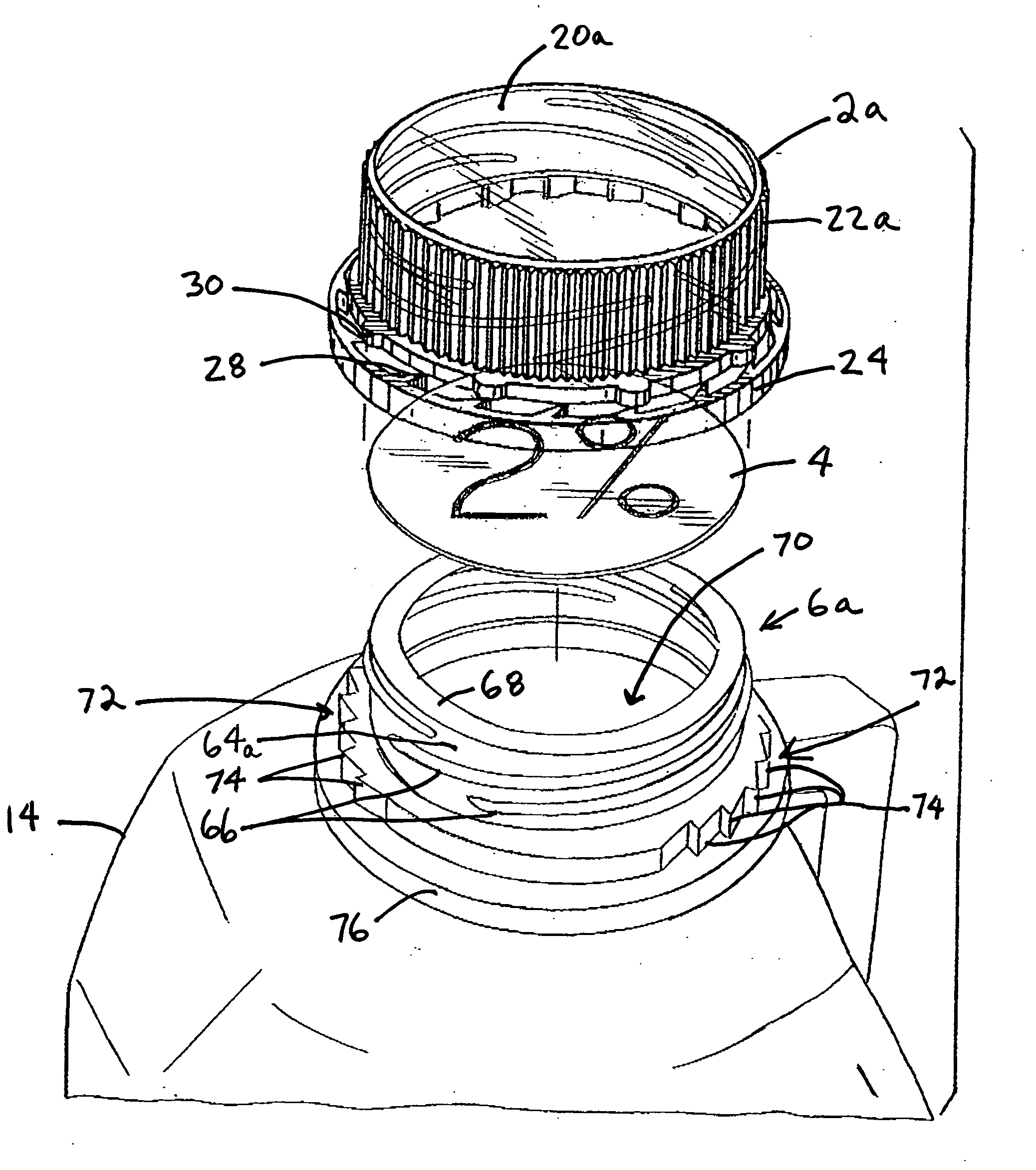
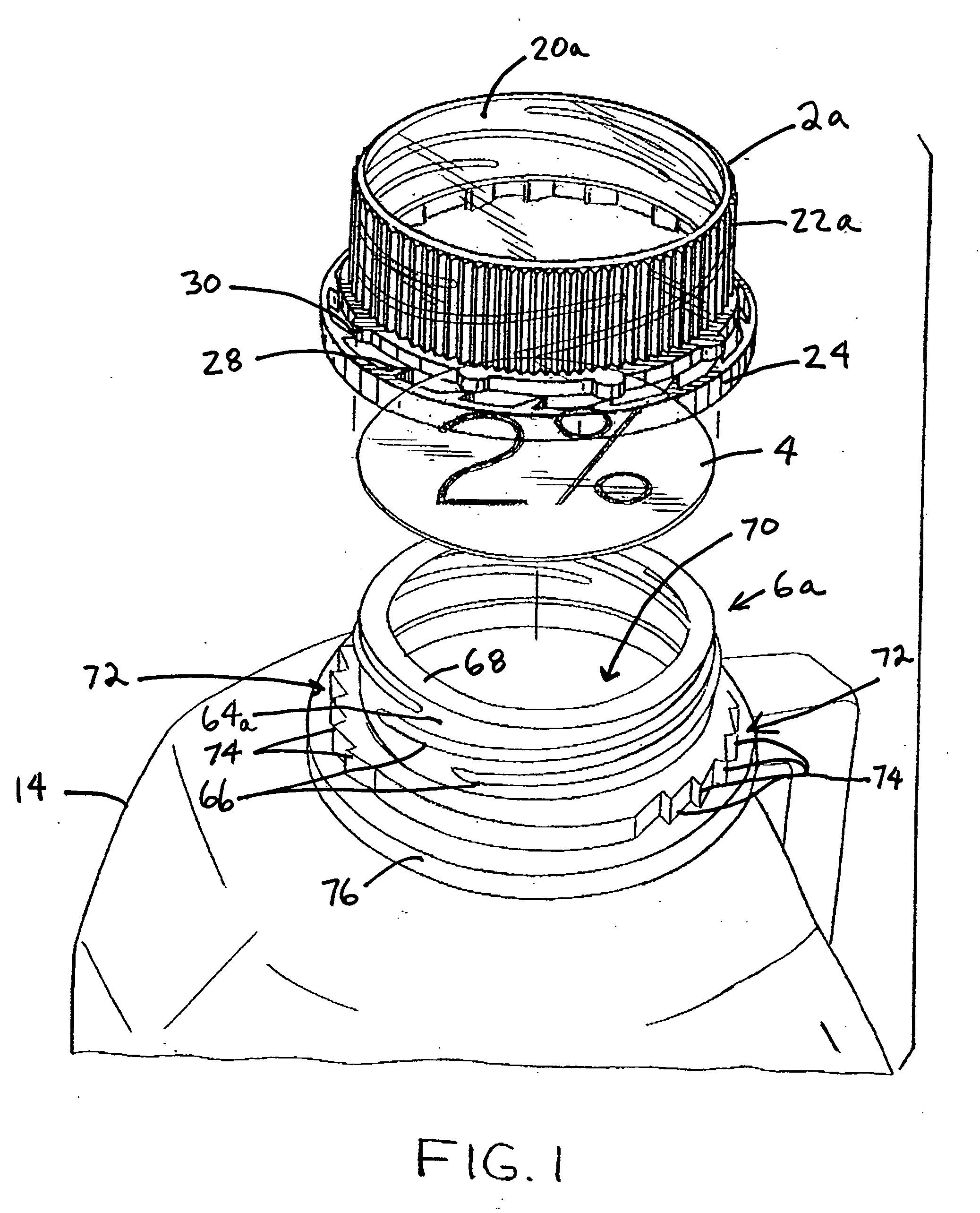
[0025]FIG. 1 generally depicts one of the preferred embodiments of the present invention. An exploded perspective view of a container 14, bottle cap 2a, liner 4, and bottle neck 6a combination is shown. As demonstrated in FIGS. 1 and 2, the cap 2a is non-opaque such that printing on the liner 4 can be perceived through the cap 2a.

[0026] The bottle cap 2a shown in FIG. 1 is a screw-on type cap 2a. Screw-on caps 2a typically comprise a circular cover 20a, a skirt 22a depending from the peripheral edge of the circular cover 20a, and a ratchet ring 24 which is frangibly attached below the skirt 22a. On the inside surface 34a of the skirt 22a are threads 26—preferably four—which are adapted to mate with corresponding threads 66 on the neck 6a of the bottle. The ratchet ring 24 has internal teeth 28 for engagement with the bottle neck 6a, which has external teeth 74. Every other one of the internal teeth 28 are attached to a plurality of semi-circular outwardly directed tabs 30 which are...


PUM


Abstract

The inventions disclosed herein include a clear cap and tamper-indicating seal combination, a translucent cap and seal combination, an improved cap embodying a raised ridge for providing a contact surface on the top of the cap, among other inventions. The preferred cap is at least partially non-opaque to allow a customer to perceive the tamper-indicating seal through the cap at the point of purchase. In a first embodiment, the tamper-indicating seal serves as a label, wherein the customer can perceive, through the cap, information such as printing which is indicative of the contents of the container. In a second embodiment, the tamper-indicating seal serves as a tamper evident seal, wherein the customer can perceive, through the cap, at the point of purchase, whether the seal has been breached. In a third embodiment, the tamper-indicating seal serves as both a label and a seal, wherein the tamper-indicating seal creates a liquid resistant seal between the cap and the opening of the container. In a forth embodiment, the tamper-indicating seal serves as both a label and a tamper evident seal. In a fifth embodiment of the present invention, a cap is provided with a raised portion on a top surface of the cap for reducing the frictional surface area of the cap during capping operations.

Description

[0001] This is a continuation-in-part application of parent application Ser. No. 11 / 222,429 filed Sep. 8, 2005.BACKGROUND OF THE INVENTIONS [0002] The inventions described herein relate to closure devices, and in particular, relate to a cap and liner (such as a tamper indicating seal or membrane) combination for bottles. The preferred cap of the present inventions is at least partially transparent or translucent to allow a customer to perceive a printed or colored liner or membrane through the cap at the point of purchase. An alternative cap of the present invention includes a raised portion or ridge on an upper surface of the cap to reduce the surface friction during capping operations. Another alternative cap of the present invention incorporates a lid which is at least partially transparent to allow a customer to perceive a printed or colored liner or membrane through the cap at the point of purchase, wherein the transparent portion is polished to increase the clarity, and incorp...

Claims


Application Information

Patent Timeline
IPC IPC(8): B65D51/00B65D41/00B65D51/20
CPCB65D41/045B65D41/3409B65D41/46B65D2251/0093B65D55/066B65D2203/02B65D2251/0015B65D51/20B65D51/18B65D55/02B65D55/024B65D55/026
Inventor HIDDING, DOUGLAS J.
Owner BLACKHAWK MOLDING
Why Eureka
Try Eureka