Enhanced fiber nodes with cmts capability

Inactive Publication Date: 2007-03-01
JUMIPER NETWORKS INC
View PDF50 Cites 24 Cited by
  • Summary
  • Abstract
  • Description
  • Claims
  • Application Information

AI Technical Summary

Benefits of technology

[0017] An enhanced CMTS, or “mini-CMTS,” as taught herein, includes programmable digital domain modulators and demodulators that permit dynamic channel assignment. These DOCSIS-compliant CMTSs are characterized by high functional density, a compact form factor, low power consumption, and integral support for the merging of analog and digital channels for transmission over digital packet networks.
[0019] Implementing all processing of each upstream channel in digital circuitry, including any baseband translation and filtering for channel selection, minimizes the number of required A / Ds, number and extent of clock sub-systems, bit-width of digital processing stages, and overall complexity. The enhanced CMTS architecture reduces connector density, reduces costs and other bulk components, and improves the system noise performance.
[0021] The distributed CMTS and packet network approach has many benefits. The data from multiple cable modems (after being demodulated by the CMTS from the received analog RF) and other upstream sources (to be discussed) is easily compressed, merged, and packet transmitted over common upstream network paths. The downstream data for multiple subscriber cable modems is likewise easily compressed, merged, and packet transmitted over common downstream network paths (for subsequent modulation by the CMTS). The compression, merging, and use of common paths, both reduces complexity and increases bandwidth utilization of the fiber plant, and thus reduces the fiber plant infrastructure cost per cable modem. Distributing CMTS functionality among multiple eFNs also reduces demands on already stretched resources at the Head End for space, power, and HVAC.
[0022] Dynamic channel allocation (including assignment and configuration) eliminates otherwise time-consuming and costly manual provisioning and re-provisioning of the enhanced CMTSs associated with installation and servicing. Dynamic channel allocation can also dramatically reduce the need to do manual node recombining (prompted by overcapacity situations) or manual channel reprovisioning (prompted by ingress noise). Channel selection and channel characteristics may be configured by transmission of a Channel Table Management Information Block (MIB), supplied over the packet network.
[0024] More broadly, programmable channel assignment and configuration enables multiple communication channels, unrelated in function or frequency, to be isolated out of a wider spectrum and then efficiently combined and commonly transmitted over a network. The ability to combine multiple diverse streams provides greater functional density and significant savings in power, bandwidth, and cost compared to previous indiscriminate entire spectrum approaches to transmitting analog channels over networks.
[0027] The present invention thus provides a selective and efficient use of available bandwidth, in that it is not necessary to transmit the entire spectrum, when only one or few portions of the spectrum are desired. Furthermore, any or all packet data transmitted between the eFN and an upstream hub or head end may be selectively compressed. Both the selective transmission of upstream channels and the compression of data reduce bandwidth requirements all along the transmission path, contributing to reductions in power, cost, and size of the associated infrastructure.

Problems solved by technology

In either architecture—using FNs or mFNs, or a combination of the two—the bandwidth of the upstream path from an FN or mFN has previously been inefficiently utilized.
The entire spectrum has been transmitted upstream because the bulk, cost and power consumption of the equipment required to process the upstream signal and pass on only the desired components has prohibited its deployment in the field.
Such components, especially the high number of connectors, add cost and bulk that would otherwise not be expended, as well as introducing new noise.

Method used


Image

  • Enhanced fiber nodes with cmts capability
  • Enhanced fiber nodes with cmts capability
  • Enhanced fiber nodes with cmts capability

Examples


Embodiment Construction

System Overview

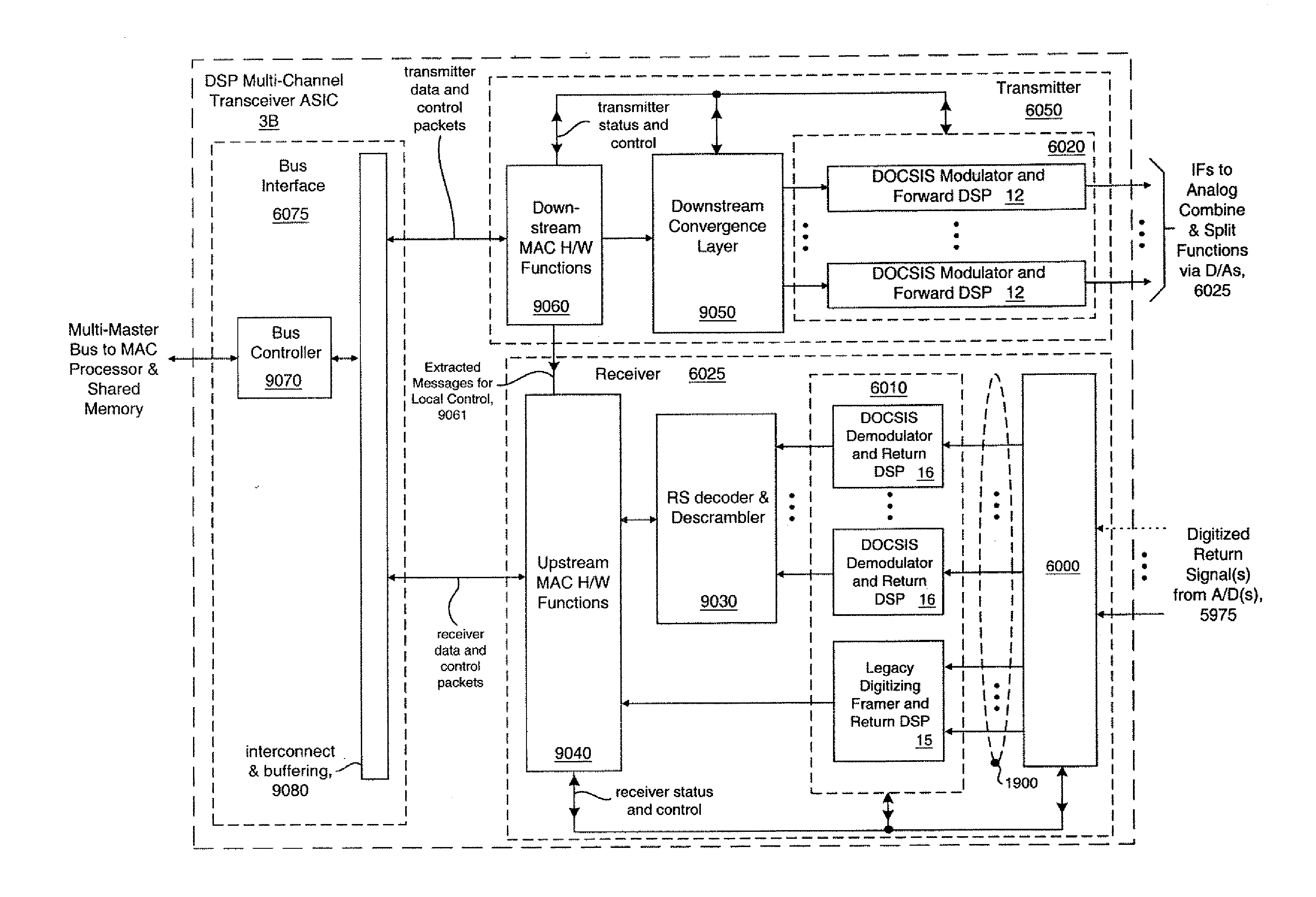
[0046]FIGS. 3A through 3D illustrate what the applicant refers to as an eFN (Enhanced FN), in accordance with the present invention. The eFN is a Fiber Node or mini Fiber Node (mFN) that includes a “mini-CMTS.” As the term is used herein, a mini-CMTS is an enhanced CMTS that is characterized by high functional density, a compact form factor, low power consumption, and integral support for the merging of analog and digital channels for transmission over digital packet networks. The mini-CMTS of the present invention provides a highly compact and cost-effective implementation, including a substantial reduction in the number of bulky connectors required. Additional illustrative detail of various aspects of the eFN and its CMTS is available in the following applications (previously incorporated by reference, above): “ENHANCED CMTS FOR RELIABILITY, AVAILABILITY, AND SERVICEABILITY,”“TRANSCEIVER CHANNEL BANK WITH REDUCED CONNECTOR DENSITY,” and “MULTIPLE INPUT, MULTIPLE O...


PUM


Abstract

Enhanced Cable Modem Termination System (CMTS) functionality, including programmable digital domain modulators and demodulators for dynamic channel assignment, is incorporated into Fiber Nodes (FNs) or mini Fiber Nodes (mFNs), yielding enhanced Fiber Nodes (eFNs). These eFns distribute CMTS functionality deep into Hybrid-Fiber-Coax Networks (HFCN) rather than centralizing the CMTS functions within a single location. Moving the cable modem terminations closer to the subscribers shortens the analog RF paths required to support cable modems. Communication of both subscriber data and CMTS control data is performed over Ethernet-compatible packet networks between the field-based CMTSs and an upstream facility (e.g., the Head End), which includes an Internet gateway. Packet data for multiple subscriber cable modems is easily compressed and merged over common network paths, reducing cabling plant complexity and increasing bandwidth utilization. This approach dramatically reduces the infrastructure cost per cable modem. Distributing CMTS functionality among multiple eFNs also reduces demands on already stretched resources at the Head End for space, power, and HVAC. For HFCN channels containing signals with modulation or encoding schemes that are unknown or best processed upstream, the invention also provides for tunneling their spectrum over the same packet network as used for the cable modem data. The channels to he tunneled are isolated using digital receivers, translated to baseband, their data framed, merged with cable modem subscriber data, and transmitted over the packet network. Upstream, the framed channel data is parsed and the original channel spectrum reconstructed to permit information recovery.

Description

CROSS REFERENCE TO RELATED APPLICATIONS [0001] This application is a Continuation-in-Part of the following patent applications, the disclosures of which are herein incorporated by reference for all purposes: [0002] U.S. patent application Ser. No. 09 / 715,992, entitled “METHODS AND APPARATUS FOR TRANSMISSION OF ANALOG CHANNELS OVER DIGITAL PACKET-BASED NETWORKS,” Liva et al., filed Nov. 16, 2000; and [0003] U.S. patent application Ser. No. 09 / 800,397, entitled “TRANSCEIVER CHANNEL BANK WITH REDUCED CONNECTOR DENSITY,” Alok Sharma, filed Mar. 5, 2001, which in turn claims priority to U.S. Provisional Patent Application Ser. No. 60 / 187,194, entitled “FREQUENCY AGILE DIGITAL TRANSCEIVER BANKS HAVING NON-UNIFORM CHANNEL WIDTH AND REDUCED CONNECTOR DENSITY,” Alok Sharma, filed Mar. 6, 2000. [0004] This application also incorporates by reference the following patent applications: Docket No. PBC.2000.108, entitled “ENHANCED CMTS FOR RELIABILITY, AVAILABILITY, AND SERVICEABILITY,” Liva et al...

Claims


Application Information

Patent Timeline
IPC IPC(8): H04N7/173H04B10/272H04J1/05H04N7/22
CPCH04B10/272H04J1/05H04L12/2801H04L12/2856H04L12/287H04L12/2898H04N21/6168H04N7/10H04N7/173H04N7/17309H04N7/22H04N21/2221H04N21/6118H04L27/3416
Inventor LIVA, VALENTINOSHARMA, ALOKSMITH, LANCEYEE, JAMES
Owner JUMIPER NETWORKS INC
Why Eureka
Try Eureka