Gas turbine gearbox

a technology of gas turbines and gearboxes, applied in the direction of gearboxes, machines/engines, efficient propulsion technologies, etc., can solve the problems of increasing production, inventory, etc., and achieve the effect of reducing duplication

Inactive Publication Date: 2007-03-01
MITROVIC LAZAR
View PDF36 Cites 2 Cited by
  • Summary
  • Abstract
  • Description
  • Claims
  • Application Information

AI Technical Summary

Benefits of technology

[0004] It is therefore an aim of the present invention to provide an improved method of manufacturing a gearbox for a gas turbine engine which minimizes duplication for different turboprop applications having differing directions of rotation.

Problems solved by technology

Providing two gearboxes, however, increases the costs of production, inventory, etc. and, accordingly, there is a need for an improved gas turbine gearbox design adapted to drive a propeller either direction.

Method used


Image

  • Gas turbine gearbox
  • Gas turbine gearbox
  • Gas turbine gearbox

Examples


Embodiment Construction

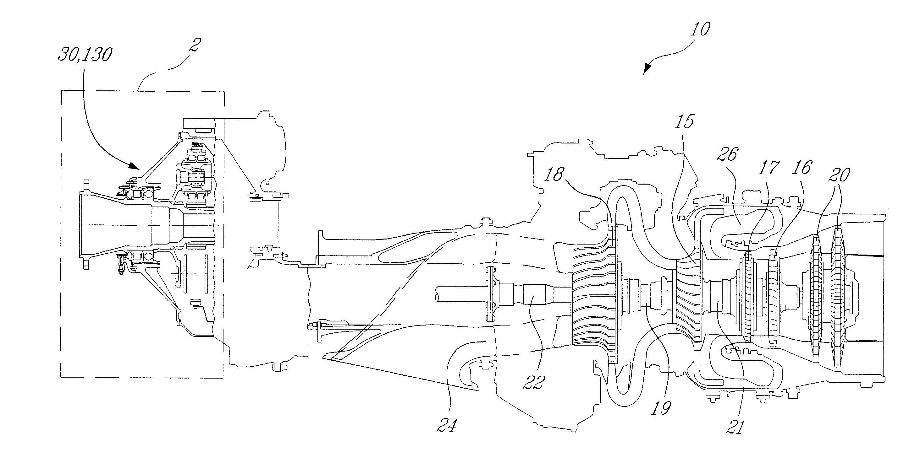
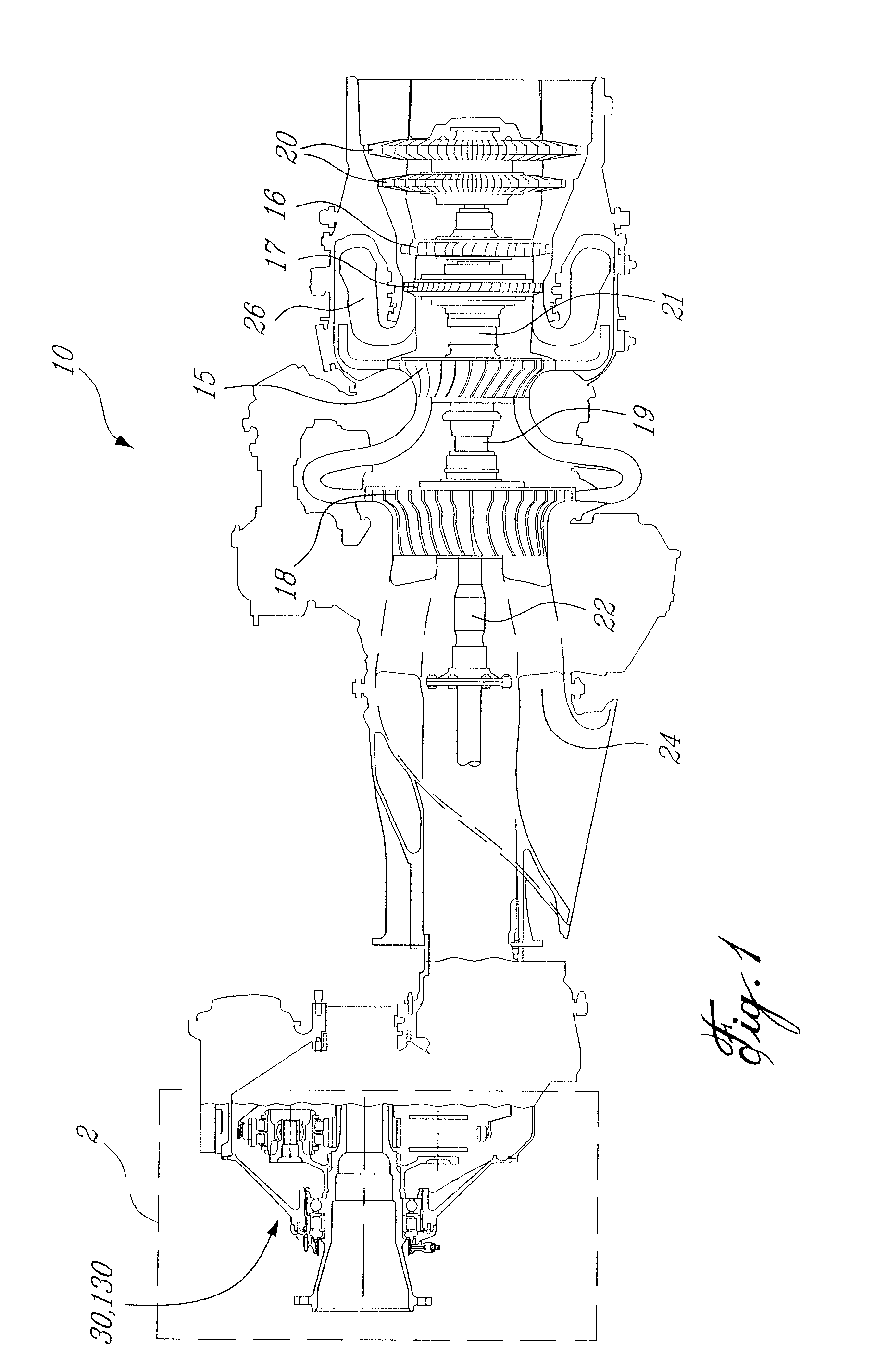
[0018]FIG. 1 illustrates a turboprop engine 10 having an offset gearbox 30,130 for driving a propeller. The engine 10 comprises a first rotating assembly including a low pressure (LP) turbine 16 and a LP compressor 18 mounted on an LP turbine shaft 19, and a second rotating assembly including a high pressure (HP) turbine 17 and a HP compressor 15 mounted on a HP turbine shaft 21. Power turbines 20 drive a power turbine output shaft 22, which provides rotational input into the gearbox 30,130.

[0019] The LP and HP compressors 18,15 draw air into the engine 10 via an annular air inlet passage 24, increasing its pressure and delivering the compressed air to a combustor 26 where it is mixed with fuel and ignited for generating a stream of hot combustion gases. The LP and HP turbines 16,17 extract energy from the hot expanding gases for respectively driving the LP and HP compressors 18,15. The hot gases leaving the LP and HP compressor turbines are accelerated again as they expand through...


PUM


Abstract

A method of manufacturing and / or providing a gearbox for rotating a propeller in a selected single one of a first and second direction is disclosed. The gearbox includes a many common components, selected irrespective of desired propeller direction, and a few unique components selected based on desired propeller direction. In one aspect the method includes casting a casing of the gearbox and machining the casing according to a selected configuration of the gear stages of the gearbox used to achieve direction of the propeller in the selected direction.

Description

CROSS-REFERENCE TO RELATED APPLICATIONS [0001] The present application is a divisional of U.S. patent application Ser. No. 10 / 817,857 filed Apr. 6, 2004, the entire specification of which is incorporated herein by reference.TECHNICAL FIELD [0002] The present invention relates to gas turbine engines, and most particularly to gearboxes of such engines. BACKGROUND OF THE INVENTION [0003] In a typical turboprop engine, the propeller rotates in only one direction and the gearbox is designed to handle the associated reacted propeller loads accordingly, in addition to transmitting the driving power. However, because the gas turbine direction is generally fixed the propeller loads are somewhat asymmetric, and the gearbox design will vary depending on which direction the propeller is intended to rotate. Thus, if a gas turbine manufacturer wishes to provide a generic gas turbine engine capable or spinning a propeller in either direction depending on the customer's preference, two different ge...

Claims


Application Information

Patent Timeline
Patent Type & Authority Applications(United States)
IPC IPC(8): F16H57/08B64D35/00B64D41/00F01D15/12F02C6/20F02C7/36F16H1/06F16H1/28
CPCB64D35/00F01D15/12F02C6/206Y10T74/19074F16H1/06F16H1/2818F02C7/36Y02T50/60
Inventor MITROVIC, LAZAR
Owner MITROVIC LAZAR
Why Eureka
Try Eureka