Display device

Active Publication Date: 2007-02-22
TRIVALE TECH
View PDF7 Cites 3 Cited by
  • Summary
  • Abstract
  • Description
  • Claims
  • Application Information

AI Technical Summary

Benefits of technology

[0008] With the foregoing in view, it is an object of the present invention to provide a display device which can decrease the screen border size and has excellent display quality.
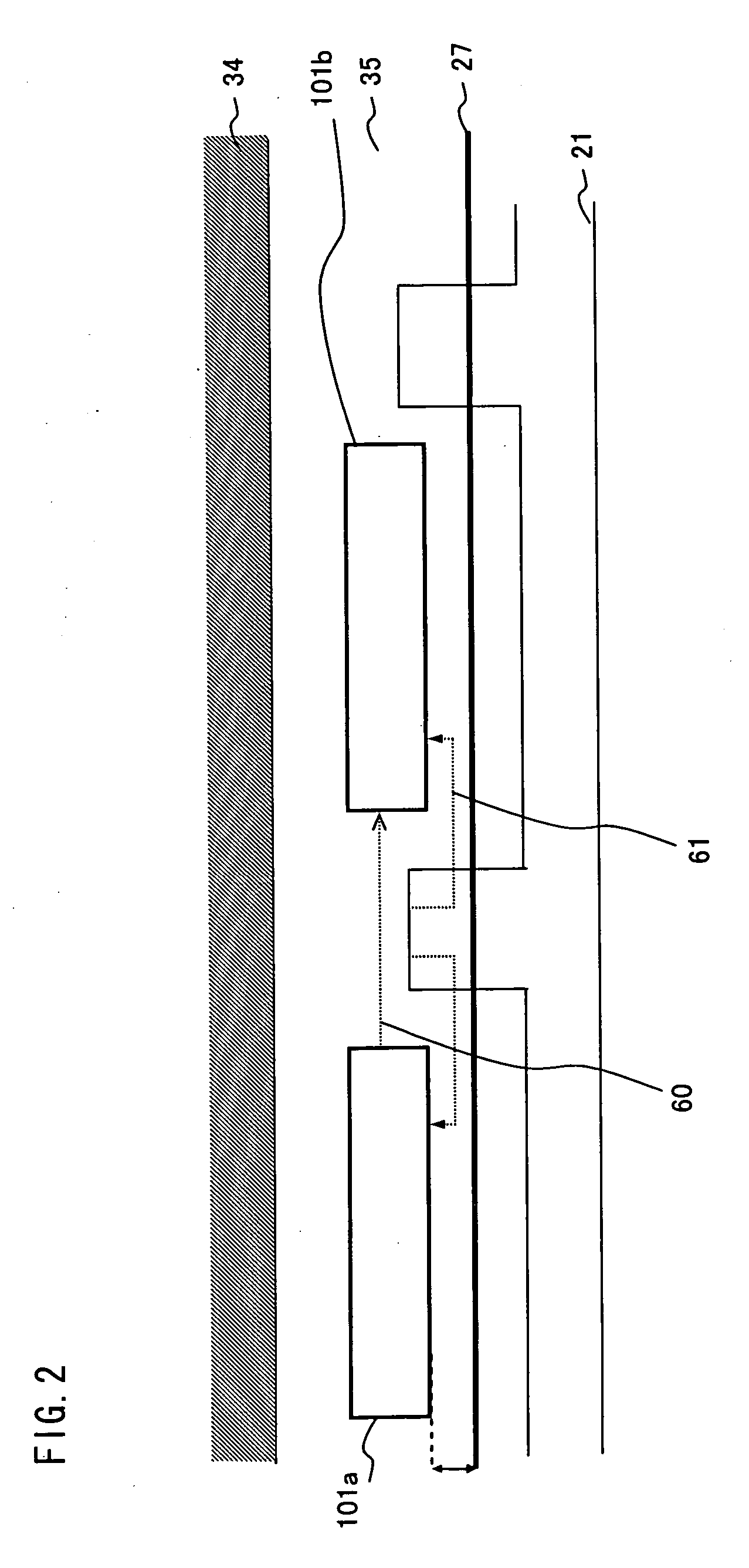
[0009] To these ends, according to one aspect of the present invention, there is provided a display device, including a display panel having an insulation substrate; a drive circuit disposed around a display area on the insulation substrate to output signals to the display panel; a plurality of bumps formed on the drive circuit; and a plurality of lines formed on the insulation substrate and connected with the bumps, wherein adjacent two or more of the plurality of bumps are electrically connected on the drive circuit, and the electrically connected two or more bumps are connected with one of the lines via an anisotropic conductive film. This can reduce the connection resistance between lines and bumps.
[0010] In the above display device, it is preferred that the drive circuit is disposed along an edge of the insulation substrate, and the electrically connected bumps are formed substantially in parallel with the edge. This can increase the width of the input line on a glass substrate, thereby reducing line resistance.

Problems solved by technology

This configuration, however, has the following problems.
Also many bumps for connection must be provided on the driver IC, so the bump configuration is restricted and the pitch between bumps cannot be freely increased.
By such an increase in the resistance between bumps and the FPC, the driver IC 101 may not operate normally or the desired voltage may not be output.
And the operation of the driver IC may have problems, which decreases the display quality.

Method used


Image

  • Display device
  • Display device
  • Display device

Examples


first embodiment

[0037] Embodiments of the present invention will now be described with reference to the accompany drawings. The following description shows the preferred embodiments of the present invention, however the scope of the present invention is not limited by the following embodiments. In the following description, composing elements denoted with a same reference symbol substantially have the same content.

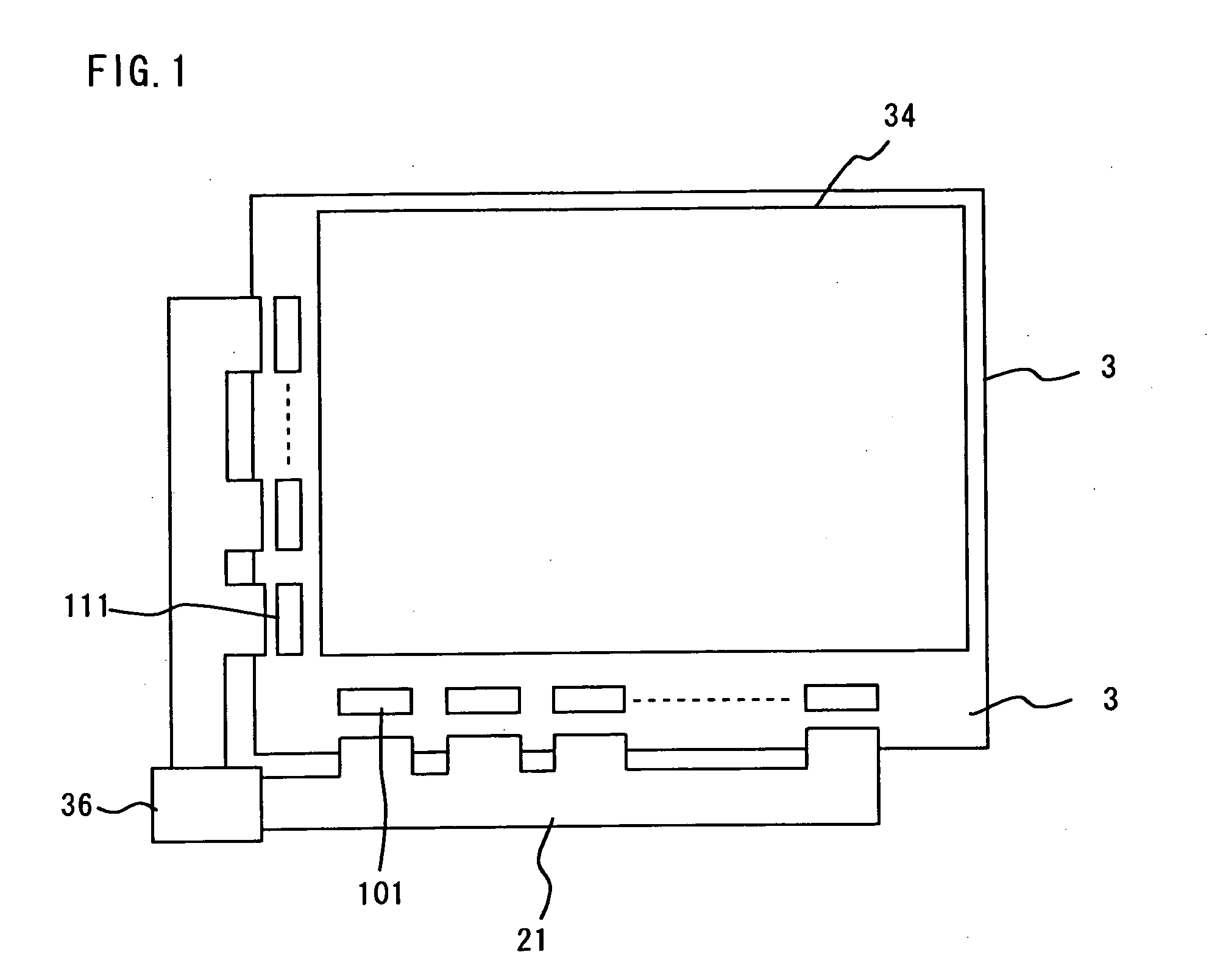
[0038] The configuration of the liquid crystal display panel 33 of the liquid crystal display device will now be described with reference to FIG. 1. FIG. 1 is a top view depicting the configuration of the liquid crystal display panel in the COG packaging type liquid crystal display device. The liquid crystal display panel 33 shown in FIG. 1 is comprised of a display area 34 which is further comprised of a plurality of pixels arrayed in a matrix, and a screen border area 35 outside of the display area 34. The liquid crystal display panel 33 is comprised of an array substrate where an arra...

second embodiment

[0066] The present embodiment will be described with reference to FIG. 10. FIG. 10 is a plan view depicting the configuration of the area around the bumps for input provided on the source driver IC of the liquid crystal display device. Compared with the first embodiment, the configuration between the FPC 21 and the bumps for input is different in the present embodiment, and description will be omitted for the configuration the same as the first embodiment.

[0067] In the present embodiment, in the FPC 21, the terminal for GND 24c and the terminal for analog power supply 23c are connected to the source driver IC 101b at the right, and the terminal for digital power supply 25c, the terminal for reference voltage at the positive polarity side 22c and the terminal for reference voltage at the negative polarity side 26c are connected with the source driver IC 101a at the left. By providing the terminal for digital power supply 25c at the left of the FPC 21, the line width of the GND 24d a...

third embodiment

[0070] The present embodiment will be described with reference to FIG. 11. FIG. 11 is a plan view depicting the configuration of the area around the bumps for input provided on the source driver IC of the liquid crystal display device. Compared with the first embodiment, the configuration between the FPC 21 and the bumps for input is different in the present embodiment, and description will be omitted for the configuration the same as the first embodiment.

[0071] According to the present embodiment, an FPC 21 is mounted at every other space between the source driver ICs, so that one FPC 21 is connected to two source driver ICs. This FPC 21a supplies all the signals and power for operating both the source driver IC 101a and the source driver IC 101b at the left and right. In other words, terminals for connecting with the source driver IC 101a are provided in the side section at the left of the FPC 21, which connect with the respective bumps for input of the source driver IC 101a via ...


PUM


Abstract

The present invention provides a display device which has a narrow screen border, and excellent display equality. The display device according to the present invention comprises a display panel comprising a glass substrate and a source driver IC which is provided along the edge of the glass substrate. The FPC is connected between the source driver ICs. At the substrate end side of the source driver IC, a bump for GND, a bump for analog power supply, a bump for digital power supply, a bump for reference voltage at the positive polarity side, and a bump for reference voltage at the negative polarity side are formed sequentially from the outer side along the flow of current. These bumps for input and the FPC are connected with the lines for input on the glass substrate. The logic signal lines and are formed along the short side of the source driver IC and along the long side at the display area side.

Description

BACKGROUND OF THE INVENTION [0001] 1. Field of the Invention [0002] The present invention relates to a display device, and more particularly to a COG packaging type liquid crystal display comprising an IC chip for driving a thin film transistor (TFT) on a glass substrate. [0003] 2. Description of the Related Art [0004] The liquid crystal display device is comprised of a liquid crystal display panel which is further comprised of two substrates between which the liquid crystal layer is held, and a surface light source unit which is installed on the rear face side of the liquid crystal display panel. The liquid crystal display panel is normally constructed by two insulation transparent substrates made of glass, which face each other, where display material, such as liquid crystals, is sandwiched, so that voltage is applied selectively to this display material. One of the substrates is a thin film transistor array substrate (hereafter called TFT array substrate) where switching elements...

Claims


Application Information

Patent Timeline
IPC IPC(8): G02F1/1345G02F1/13G09F9/00H01L21/60
CPCG02F1/13452H01L2924/0002H01L2924/00G02F1/1345
Inventor IWANAGA, HIROFUMINOUMI, SHIGEAKIMORISHITA, HITOSHIUEDA, HIROSHI
Owner TRIVALE TECH
Why Eureka
Try Eureka