
Optical resin film and polarizing plate and liquid crystal display using same

a technology of optical resin film and polarizing plate, applied in non-linear optics, instruments, optics, etc., can solve the problems of narrow viewing angle, inability to meet the requirements of using techniques, and inability to accurately determine the viewing angle, so as to improve the contrast of the viewing angle, the effect of reducing light leakag

Active Publication Date: 2007-02-22
FUJIFILM CORP
View PDF1 Cites 8 Cited by
  • Summary
  • Abstract
  • Description
  • Claims
  • Application Information

AI Technical Summary

Benefits of technology

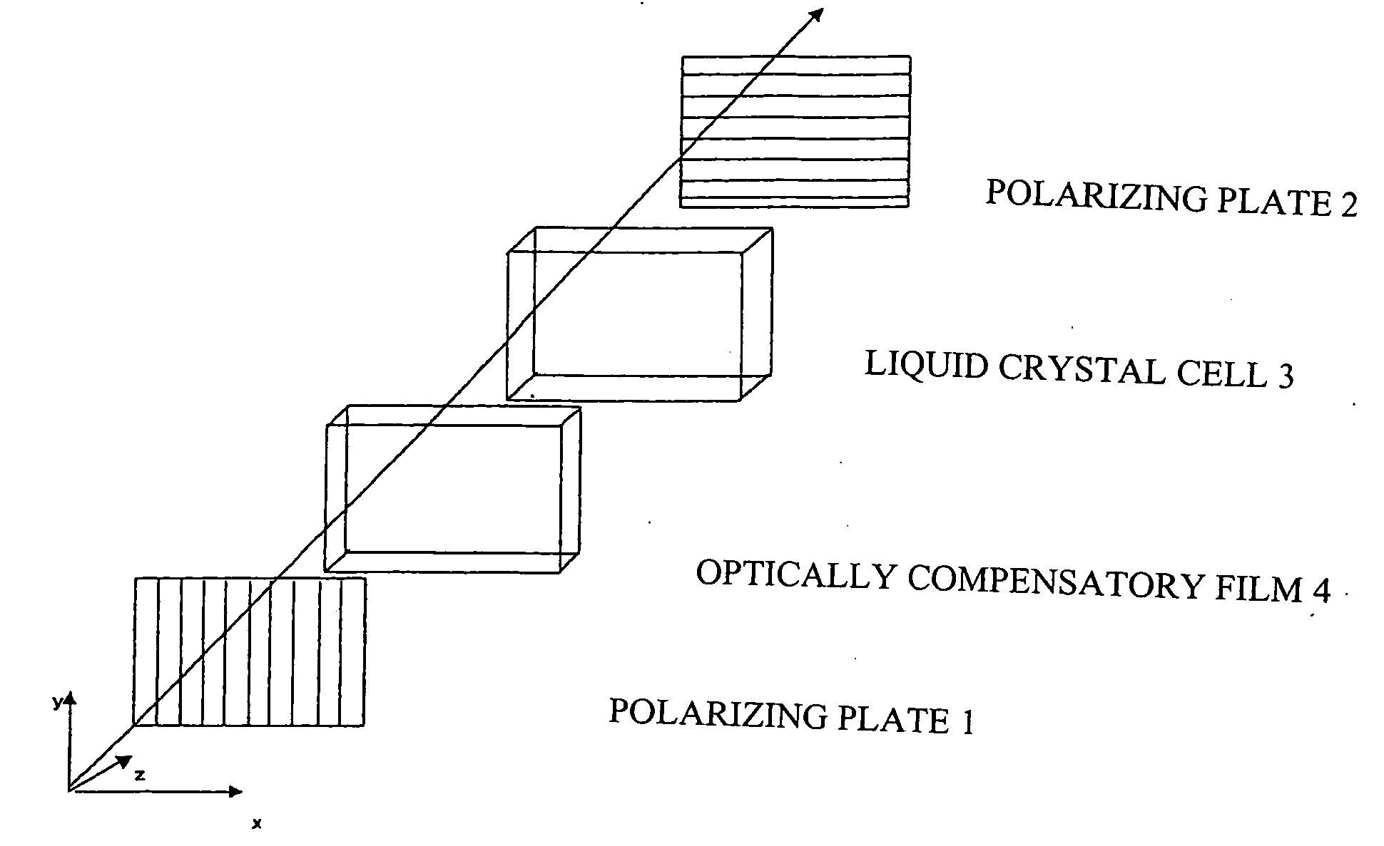
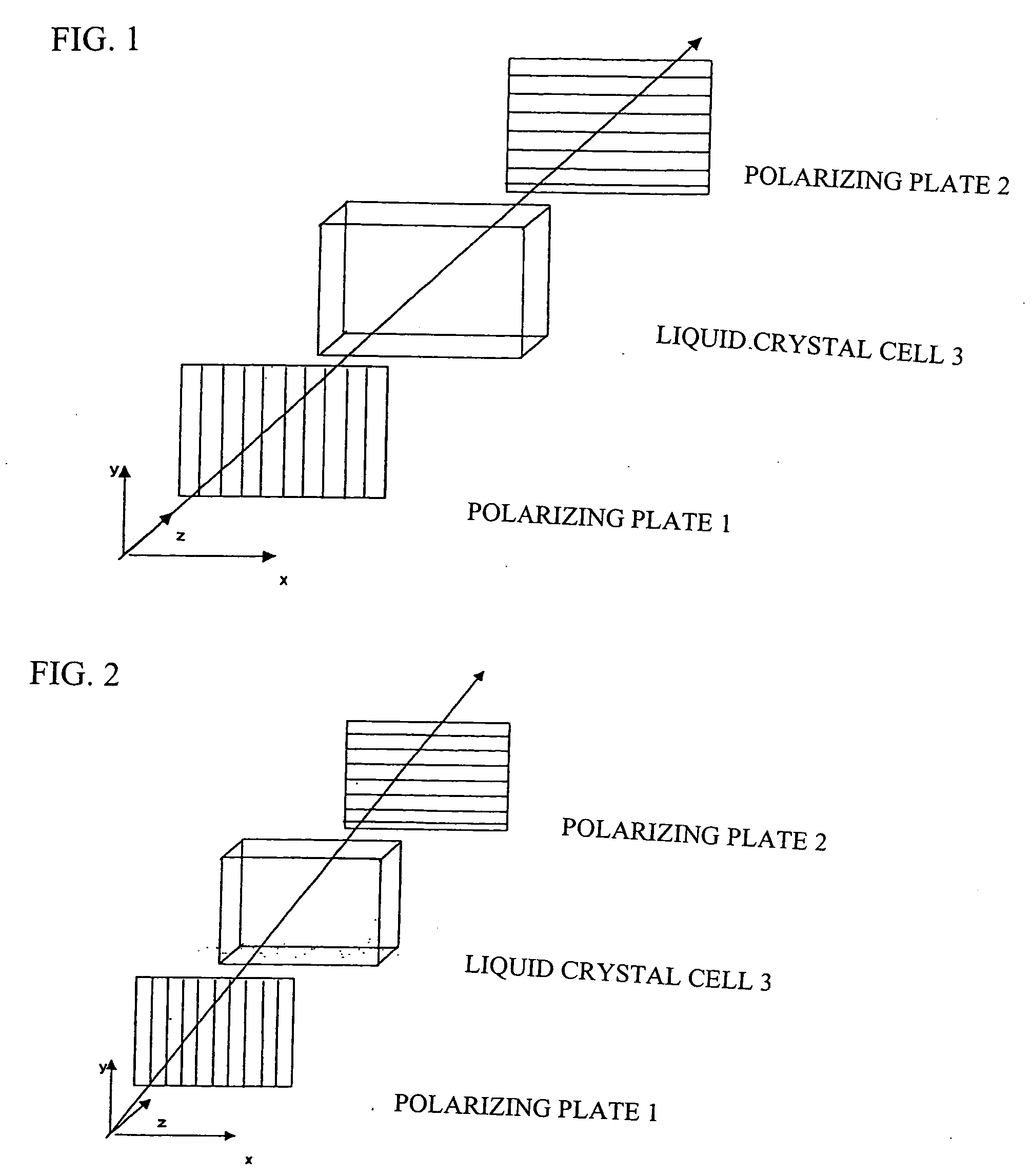
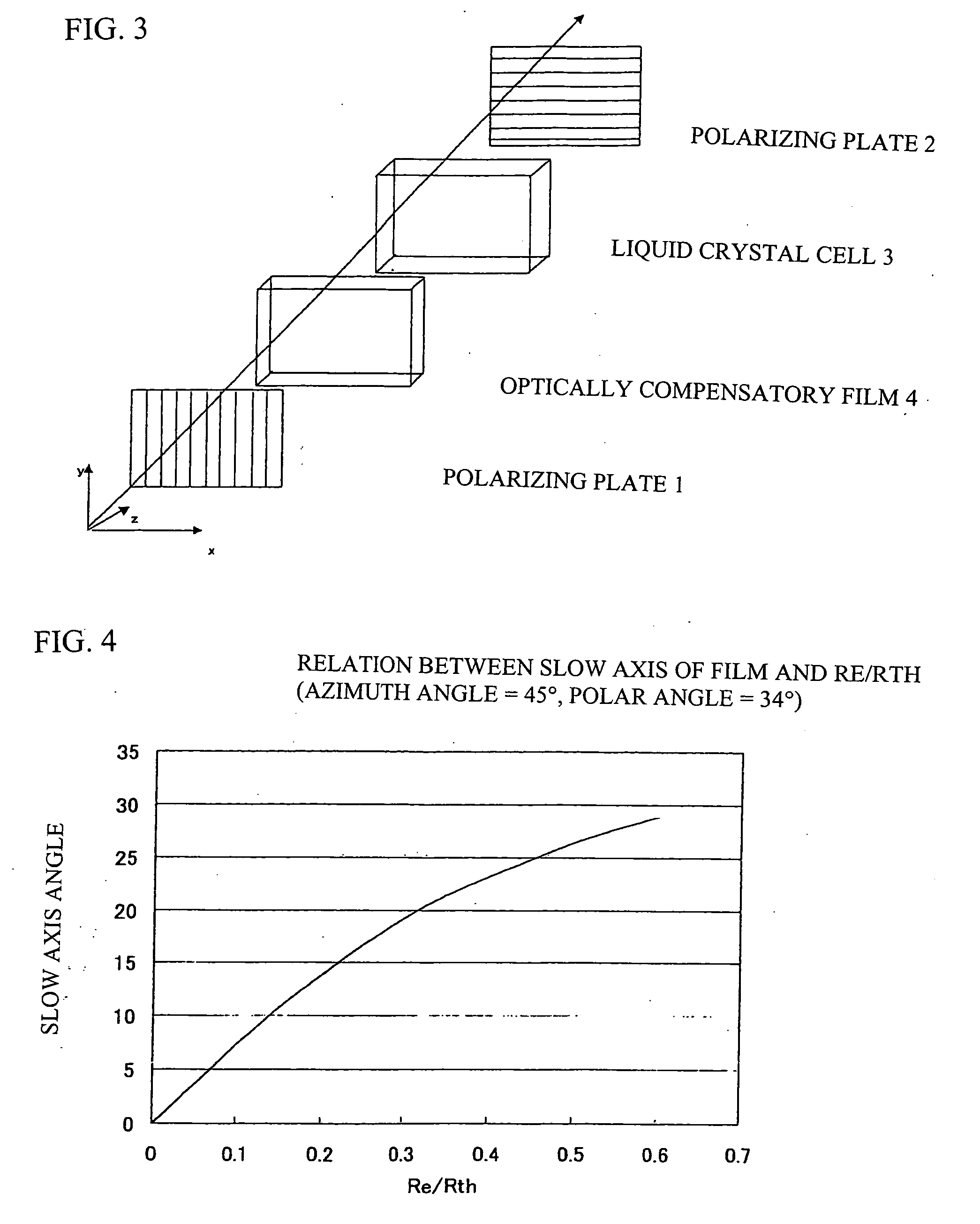
[0008] An object of an illustrative, non-limiting embodiment of the invention is to provide an optical resin film which shows no change in the optical characteristics due to changes in temperature or humidity, has a high contrast ratio over a broad range and can regulate color shift, and a polarizing plate and a liquid crystal display by using the same.
[0011] In an aspect of the present invention that has been completed based on the findings obtained as the results of intensive studies by the inventors, the in-plane retardation and the thickness-direction retardation of an optical resin film are independently controlled and the optically optimum values thereof are determined by selecting appropriate materials and production methods so as to enable viewing angle compensation at almost every wavelength in the black display of a liquid crystal cell, in particular, a VA mode liquid crystal cell. As a result, the liquid crystal display of the invention shows relieved light leakage in an oblique direction and largely improved viewing angle contrast. In the liquid crystal display of the invention, furthermore, light leakage in an oblique direction in black display can be suppressed almost all over the visible light range. Thus, color-shift depending on viewing angle in black display is largely improved. According to an aspect of the invention, therefore, it is possible to provide an optical resin film which suffers from no change in optical characteristics due to changes in temperature or humidity and shows a high contrast ratio over a broad range and the color shift of which can be regulated, and a polarizing plate and a liquid crystal display using the same.

Problems solved by technology

In a liquid crystal display for a wide-screen TV likely watched from various angles, however, accurate viewing angle-dependency is required and this requirement cannot be fulfilled by using the techniques as discussed above.
However, the VA mode suffers from a problem that though it provides almost complete black display in the normal line direction of the panel, light leakage arises in observing the panel from an angle and thus the viewing angle is narrowed.
However, color shift as discussed above cannot be improved even by using such films as reported in Japanese Patent No. 3273046.

Method used


Image

  • Optical resin film and polarizing plate and liquid crystal display using same
  • Optical resin film and polarizing plate and liquid crystal display using same
  • Optical resin film and polarizing plate and liquid crystal display using same

Examples


example 1

[0247] (Formation of Film 1) To 60 parts of 6-methyl-1,4,5,8-dimethano-1,4,4a,5,6,7,8,8a-octahydronaphthalene (hereinafter abbreviated as MTD), 10 parts of a 15% cyclohexane solution of triethyl aluminum employed as a polymerization catalyst, 5 parts of triethylamine and 10 parts of a 20% cyclohexane solution of titanium tetrachloride were added. After ring-opening polymerization in cyclohexane, the obtained ring-opened polymer was hydrogenated with a nickel catalyst to give a polymer solution. This polymer solution was solidified in isopropyl alcohol and dried to give a powdery resin. The number-average molecular weight of this resin was 40,000, the hydrogenation ratio thereof was 99.8% or more and Tg thereof was 142° C.

[0248] This powdery resin was melted at 250° C. and pelletized. The obtained pellets were melt-extruded from a T-die of 300 mm in width with the use of a uniaxial extruder provided with a 40 nm full flight screw and then wound up with three cooling rolls of 300 mm ...

example 2

[0253] The film 1 obtained in Example 1 was freely uniaxially stretched in the traveling direction at 185° C. at a stretching ratio of 15% to give a stretched and orientated film. Table 1 shows the optical performance thereof.

[0254] The films 2 to 4 were also stretched under the conditions as specified in Table 1. Table 1 shows the optical performances thus obtained too.

[0255] In Tables 1 to 3, the numerical values given in the columns (A) to (D) respectively indicate the following values.

[0256] (A) Re(450) / Re(550)

[0257] (B) Re(650) / Re(550)

[0258] (C) (Re(450) / Rth(450)) / (Re(550) / Rth(550))

[0259] (D) (Re(650) / Rth(650)) / (Re(550) / Rth(550))

TABLE 1Un-StretchingStretchingFilmstretchedtemp.ratioThicknessReReReRthRthRthNo.raw film(° C.)(%)(μm)(450)(550)(650)(450)(550)(650)ABCD2-11185151203545554550550.7781.2220.8641.111Invention2-2218525804255685260680.7641.2360.8811.091Invention2-3320025906572806770720.9031.1110.9431.080Invention2-4418520955865725860630.8921.1080.9231.055Invention

example 3

[0260] The films 1 to 4 obtained in Example 1 were free-uniaxially stretched in the traveling direction at 185° C. at a stretching ratio of 25%. Next, these films were relieved in the traveling direction at 25% to give stretched and orientated films. Table 2 shows the stretching conditions and optical performances.

TABLE 2Un-WidthwiseLengthwisestretchedStretchingstretchingrelievingThick-Filmrawtemp.ratiorationessReReReRthRthRthNo.film(° C.)(%)(%)(μm)(450)(550)(650)(450)(550)(650)ABCD3-1118525251204855601251301350.8731.0910.9081.051Invention3-222003530757075801481501550.9331.0670.9461.032Invention3-331903020956875831551601650.9071.1070.9361.073Invention3-442003025906065701311301280.9231.0770.9161.094Invention


PUM


Abstract

An optical resin film is provided and fulfills the following formulae (A) to (D) concerning retardations and is formed by using a polymer or a copolymer of a cycloolefin compound: 0.1<Re(450) / Re(550)<0.95;  (A) 1.03<Re(650) / Re(550)<1.93;  (B) 0.4<(Re(450) / Rth(450) / Re(550) / Rth(550))<0.95; and  (C) 1.05<(Re(650) / Rth(650) / Re(550) / Rth(550))<1.9.  (D)

Description

FIELD OF THE INVENTION [0001] The invention relates to an optical resin film and a polarizing plate and a liquid crystal display using the same. BACKGROUND OF THE INVENTION [0002] Liquid crystal displays have been widely used in monitors of personal computers and mobile telephones, TV sets and so on because of having a number of merits such as running at low voltage, requiring little electricity and being available in downsized and thinned modes. These liquid crystal displays have been proposed in various modes depending on the aligned states of liquid crystal molecules in liquid crystal cells. Among all, the TN mode, wherein liquid crystal molecules are aligned at a twist angle of about 90° from the lower substrate of a liquid crystal cell toward the upper substrate, has been mainly employed. [0003] A liquid crystal display is usually made up of a liquid crystal cell, an optically compensatory sheet and a polarizer. As the optically compensatory sheet, which is employed to relieve ...

Claims


Application Information

Patent Timeline
IPC IPC(8): G02F1/1335
CPCG02F1/13363G02F2001/133635G02F2202/40G02F2413/01G02F1/133635
Inventor OHGARU, IKUKOSUGIYAMA, SUSUMU
Owner FUJIFILM CORP
Learn More