
Method and system for adaptive maximum intensity projection ray casting

a maximum intensity projection and projection ray technology, applied in the field of volume data rendering, can solve the problems of jitter effect, mip ray casting is a computationally expensive process, and no single image slice is able to visualize the whole surface of the hear

Active Publication Date: 2007-02-22
FOVIA
View PDF22 Cites 35 Cited by
  • Summary
  • Abstract
  • Description
  • Claims
  • Application Information

AI Technical Summary

Benefits of technology

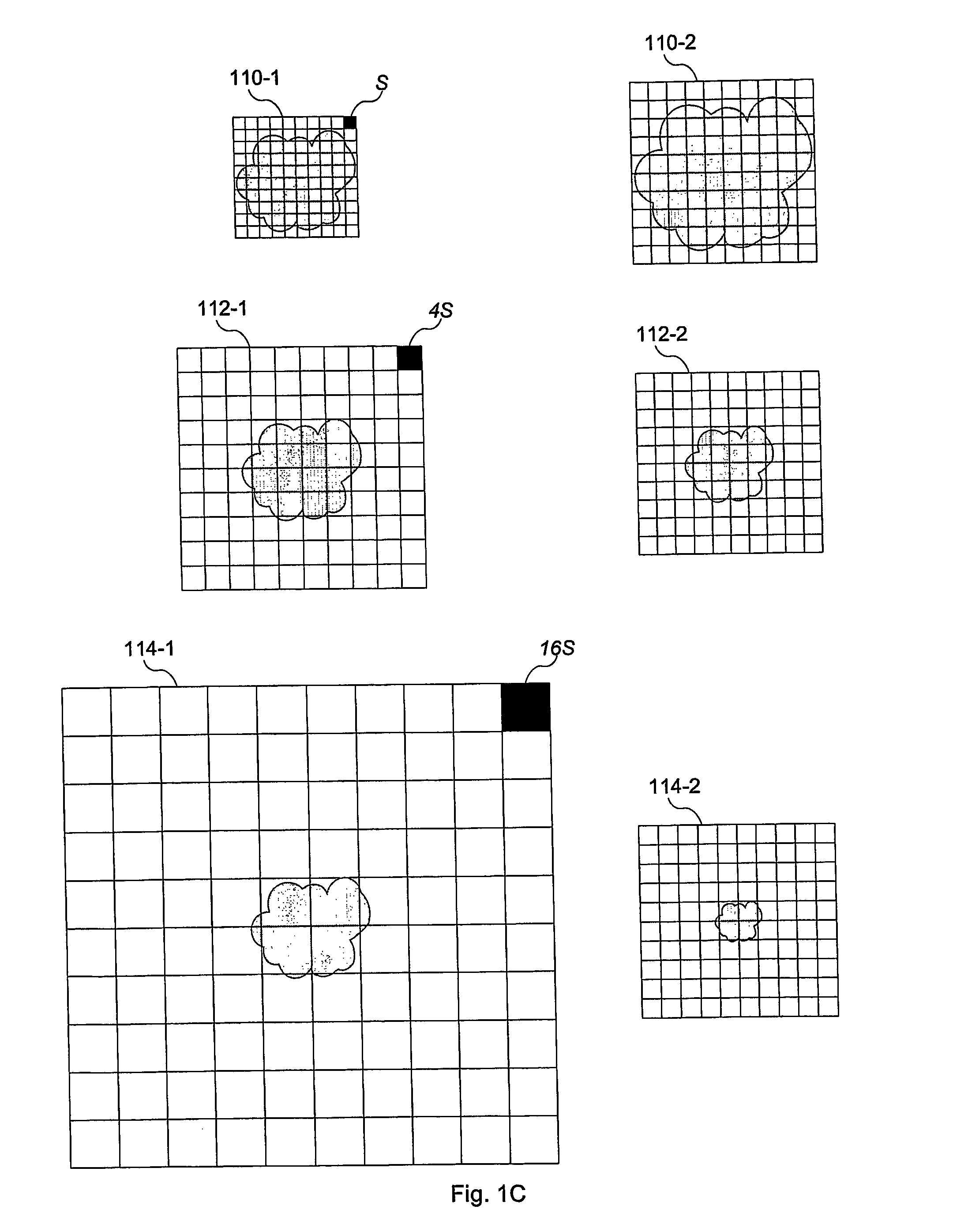
"The present invention is an adaptive MIP ray casting method and system that generate high-quality 2-D images of 3-D objects embedded in a 3-D dataset using adaptive data representation, MIP ray casting, and data interpolation techniques. The method and system first fragment the 3-D dataset into multiple sub-volumes of different sizes and construct a data structure associating nodes of the dataset with the sub-volumes. Each ray interacts with a sub-volume and updates its data value record if it identifies a higher data value along its ray path. The method and system optimize the locations of the ray origins on a 2-D radiation plane to capture the characteristics of the 3-D internal structures embedded within the 3-D dataset. The computational cost and image resolution of the MIP ray casting algorithm are determined primarily by the number and density of the rays cast from the 2-D radiation plane."

Problems solved by technology

Going back to the CT example discussed above, even though a doctor can arbitrarily generate 2-D image slices of the heart by intercepting the image volume in any direction, no single image slice is able to visualize the whole surface of the heart.
First, MIP ray casting is a computationally expensive process.
However, many of these algorithms achieve their efficiency by sacrificing the quality of the generated 2-D images.
For example, a common problem with discrete representation of a continuous object is the jitter effect, which is most obvious when a user zooms in to view more details of the continuous object.
If the jitter effect is not carefully controlled, it may significantly corrupt the quality of an image generated by a MIP ray casting algorithm.

Method used


Image

  • Method and system for adaptive maximum intensity projection ray casting
  • Method and system for adaptive maximum intensity projection ray casting
  • Method and system for adaptive maximum intensity projection ray casting

Examples


examples

[0142]FIGS. 13A and 13B provide an example of two images generated from a 3-D CT scan dataset using adaptive MIP ray casting according to one embodiment the present invention. The two images are substantially similar except that a pixel value in FIG. 13A is only dependent upon its respective maximum data value identified along the ray path according to a predefined screen transfer function, while a pixel value in FIG. 13B is further weighted by the distance between the image plane and the location of the maximum data value in the image volume. As a result, the same maximum data values identified at different parts of the image volume may cause different pixel values on the image of FIG. 13B, offering certain 3-D perspectives to the viewer. For example, the two image sections 1320 and 1340 of the femur bone in FIG. 13A have virtually the same brightness, while the same two sections 1360 and 1380 in FIG. 13B have different brightness. In particular, since section 1360 is farther away ...


PUM


Abstract

The adaptive MIP ray casting system first fragments a 3-D dataset into multiple sub-volumes and constructs an octree data structure with each sub-volume being associated with one node of the octree data structure. The system then establishes a 2-D image plane and selectively launches a plurality of rays towards the 3-D dataset, each ray adaptively interacting with a subset of the sub-volumes and identifies the maximum data value along the ray path. The maximum data value is then converted into a pixel value on the 2-D image plane. Finally, the system interpolates pixel values at those locations where no pixel value is generated by ray casting and thereby generates a 2-D image of the 3-D dataset.

Description

FIELD OF THE INVENTION [0001] The present invention relates generally to the field of volume data rendering, and more particularly, to a method and system for rendering a volume dataset using adaptive data representation, ray casting, and data interpolation techniques. BACKGROUND OF THE INVENTION [0002] Visualization of the internal structure of 3-D objects on a 2-D image is an important topic within the field of computer graphics and has been applied to many industries, including medicine, geoscience, manufacturing, and drug discovery. [0003] For example, a CT scanner can produce hundreds or even thousands of parallel 2-D image slices of a patient's body including different organs, e.g., a heart, each slice including a 2-D array of data values and each data value representing a scalar attribute of the body at a particular location, e.g., density. All the slices are stacked together to form an image volume or a volumetric dataset of the patient's body with the heart embedded therein...

Claims


Application Information

Patent Timeline
Patent Type & Authority Applications(United States)
IPC IPC(8): G06T15/50
CPCG06T15/06G06T17/005G06T15/83G06T15/08
Inventor BUYANOVSKI, GEORGE
Owner FOVIA
Learn More