
Emission control driver and organic light emitting display device having the same and a logical or circuit for an emission control driver for outputting an emission control signal

a technology of emission control and emission control signal, which is applied in the direction of digital storage, instruments, computing, etc., can solve the problems of large power consumption, large lcd response speed, and large power consumption of lcd, and achieve the effect of reducing the size of the electroluminescent (el) panel used for the glass substrate with the oled and reducing the cost of production

Active Publication Date: 2007-02-22
SAMSUNG DISPLAY CO LTD
View PDF8 Cites 43 Cited by
  • Summary
  • Abstract
  • Description
  • Claims
  • Application Information

AI Technical Summary

Benefits of technology

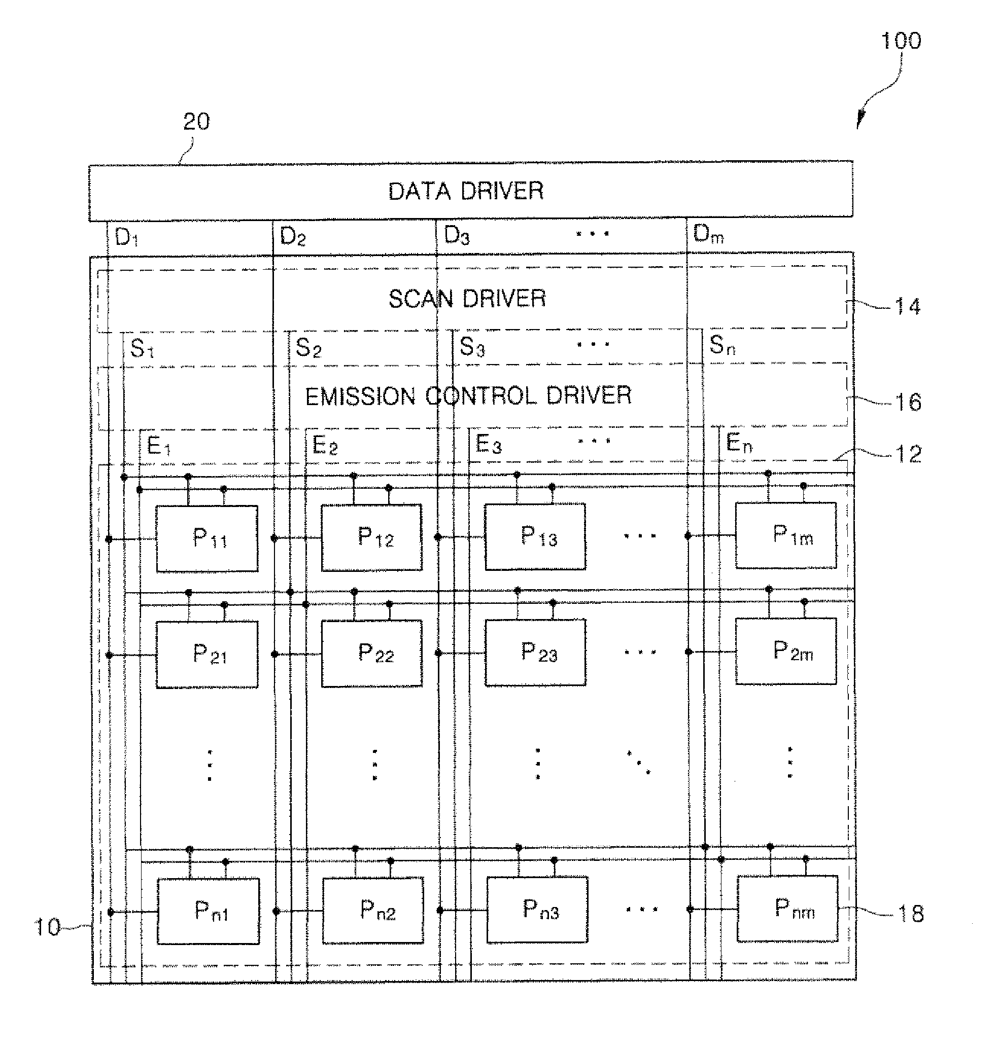
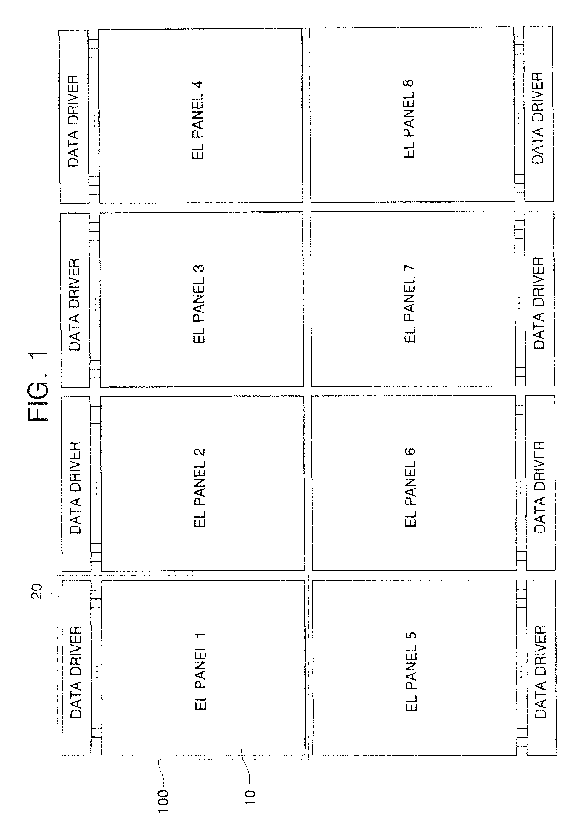
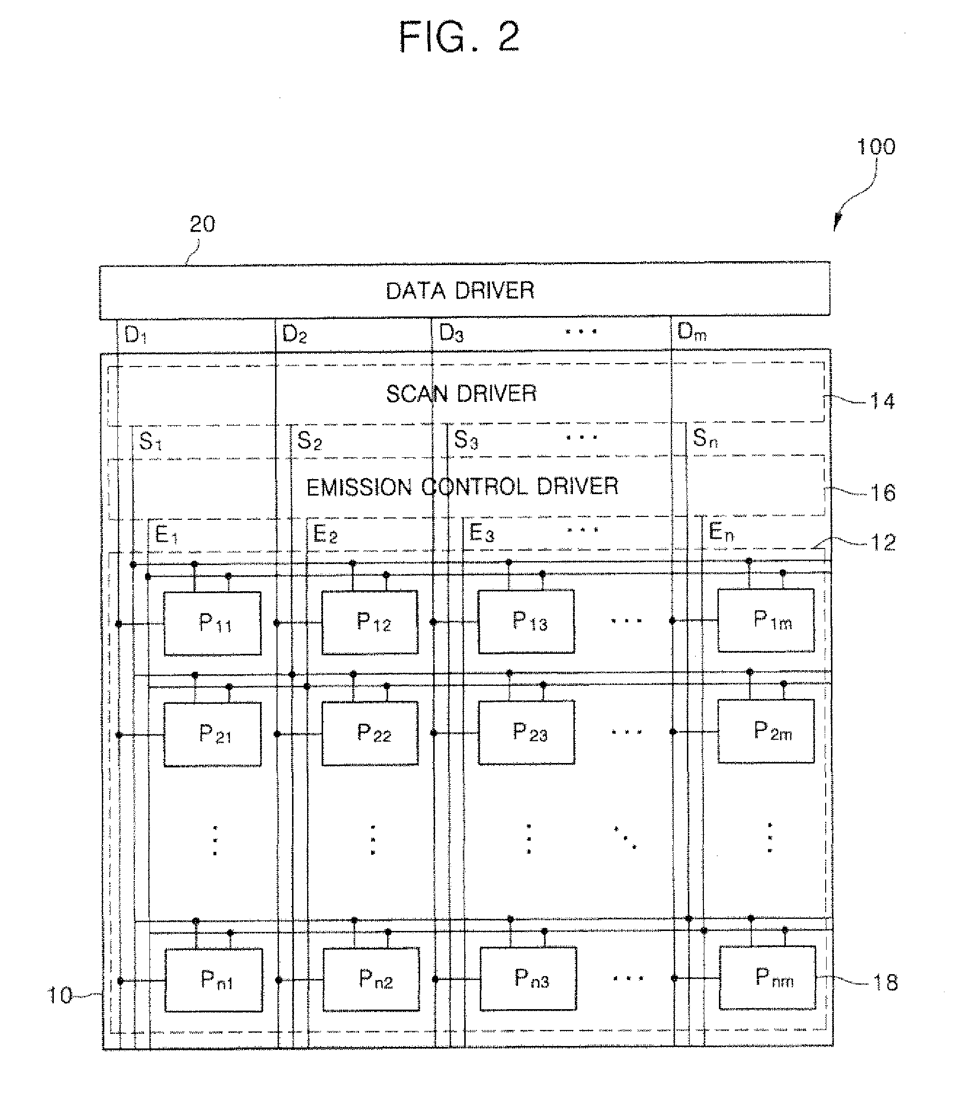
[0017] This invention provides an emission control driver which is designed as a system-on-panel (SOP) type in an electroluminescent (EL) panel and generates emission signals to control the emission of pixels for an organic light emitting display (OLED) device.

Problems solved by technology

Among these FPDs, the PDP may have a large screen, but suffers from low luminance and poor luminous efficiency resulting in high power consumption.
Moreover, the LCD has a relatively slow response speed and consumes a large quantity of power since it employs a backlight.
Nevertheless, when the OLED is constructed to have a large screen, the dimensions of an electroluminescent (EL) panel used for a glass substrate with the OLED are limited by fabricating process limitations.
Also, if the screen is too large, there is a greater probability of a defect occurring somewhere on the screen.
Thus, a reduction in yield is unavoidable, and it is difficult to obtain uniformity across the screen.
These methods are costly and complicate the modules because the drivers should be separately designed and electrically connected to one another.
The SOP technique reduces the area of the drivers, in addition to the cost and labor associated with designing integrated circuits (ICs) for the drivers.
It is currently still difficult to design the data driver within a panel because the data driver needs a high driving frequency.

Method used


Image

  • Emission control driver and organic light emitting display device having the same and a logical or circuit for an emission control driver for outputting an emission control signal
  • Emission control driver and organic light emitting display device having the same and a logical or circuit for an emission control driver for outputting an emission control signal
  • Emission control driver and organic light emitting display device having the same and a logical or circuit for an emission control driver for outputting an emission control signal

Examples


Embodiment Construction

[0034] The invention is described more fully hereinafter with reference to the accompanying drawings, in which exemplary embodiments of the invention are shown. This invention may, however, be embodied in many different forms and should not be construed as limited to the exemplary embodiments set forth herein. Rather, these exemplary embodiments are provided so that this disclosure is thorough, and will fully convey the scope of the invention to those skilled in the art. In the drawings, the size and relative sizes of layers and regions may be exaggerated for clarity. Like reference numerals in the drawings denote like elements.

[0035] It will be understood that when an element such as a layer, film, region or substrate is referred to as being “on” another element, it can be directly on the other element or intervening elements may also be present. In contrast, when an element is referred to as being “directly on” another element, there are no intervening elements present.

[0036]FIG...


PUM


Abstract

An organic light emitting display (OLED) device using a tiling technique including a system-on-panel (SOP)-type emission control driver. The emission control driver includes a shift register and a logical operation portion having a plurality of logic gates, each of which receives output signals from the shift register and performs a logical OR operation on the received signals. An active load of each of the logic gates is controlled using two output signals and two inverted output signals of two adjacent flip-flops. Also, each of the logic gates performs a logical OR operation on the two output signals of the two adjacent flip-flops and generates an emission control signal. The flip-flops and the logic gates of the emission control driver include positive channel metal oxide semiconductors (PMOS) transistors.

Description

CROSS-REFERENCE TO RELATED APPLICATION [0001] This application claims priority to and the benefit of Korean Patent Application No. 10-2005-0075428, filed on Aug. 17, 2005, and Korean Patent Application No. 10-2005-0075429, filed on Aug. 17, 2005, which are incorporated herein by reference for all purposes as if fully set forth herein. BACKGROUND OF THE INVENTION [0002] 1. Field of the Invention [0003] The present invention relates to an emission control driver and an organic light emitting display (OLED) device having the same and, more particularly, to a system-on-panel (SOP)-type emission control driver which generates signals to control emission of pixels and an OLED device having the same. [0004] 2. Discussion of the Background [0005] Flat panel displays (FPDs) have been developed because they can be made smaller and lighter than display devices using cathode ray tubes (CRTs). In turn, FPD technology has given rise to liquid crystal displays (LCDs), field emission displays (FEDs...

Claims


Application Information

Patent Timeline
Patent Type & Authority Applications(United States)
IPC IPC(8): G09G3/36
CPCG09G3/3233G09G3/3266G09G2300/0408G09G2300/0417G09G2300/0819G09G2300/0852G09G2300/0861G09G2310/0221G09G2310/0262G09G2330/021G11C19/00G11C19/184
Inventor CHUNG, BO-YONG
Owner SAMSUNG DISPLAY CO LTD
Learn More