
Device for fixing pipes to supporting structures

a technology for fixing devices and pipes, applied in the direction of stand/trestles, kitchen equipment, domestic applications, etc., can solve the problems of obstructing pipes, obstructing pipes, awkward positioning of the closure bolts of strips, etc., and achieve the effect of convenient operation

Inactive Publication Date: 2007-02-22
MORETTO SPA
View PDF8 Cites 27 Cited by
  • Summary
  • Abstract
  • Description
  • Claims
  • Application Information

AI Technical Summary

Benefits of technology

"The present invention provides a device for fixing pipes to supporting structures that can securely hold pipes without deforming them, allow for a compact arrangement of multiple pipes, and provide easy access to locking bolts. The device is made up of two C-shaped circular arc-like strips that surround the pipe and a bracket with cantilevered wings that hold the strips in place. The strips have teeth that fit into engagement portions on the bracket, and there are perforated portions for the insertion of bolts. The technical effects of this device include effective securing of pipes, compact arrangement of multiple pipes, easy access to bolts, and easy adjustment of pipe position during installation."

Problems solved by technology

In the case of thin pipes, the pipe is squeezed in the portion of contact with the upright, causing an internal bulge.
This bulge in practice tends to obstruct the pipe partially; in the case of a flow of solid particles which can flow therein, such as for example granules of plastic material loaded with glass fiber, the granules strike the bulge, producing in the long term, due to an abrasive effect, a laceration of the pipe in the point of impact.
Another problem linked to this type of fixing collar is related to the fact that when it is necessary to fix a plurality of pipes close to each other in parallel, the closure bolt of the strips is positioned awkwardly.
Moreover, with a collar of this type, the alignment of the pipe occurs with difficulty, since said collar is fixed on the upright only when the pipe presses on said upright; it is therefore difficult to align the pipes correctly.
However, with this type of collar, when it is necessary to have a plurality of pipes arranged side-by-side and parallel, said pipes are scarcely compact, since they are necessarily spaced by the width of the perforated flat portions.

Method used


Image

  • Device for fixing pipes to supporting structures
  • Device for fixing pipes to supporting structures
  • Device for fixing pipes to supporting structures

Examples


Embodiment Construction

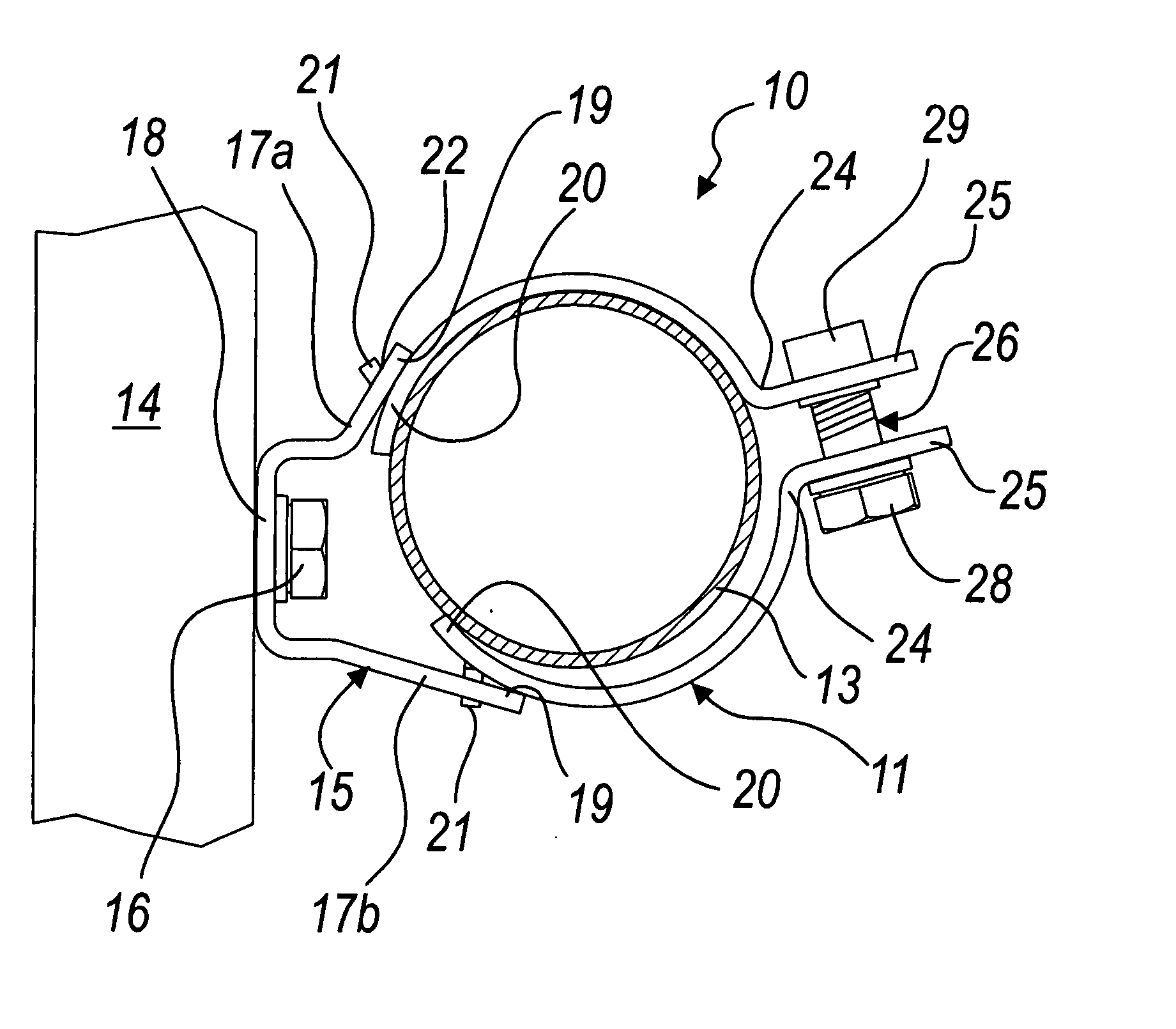
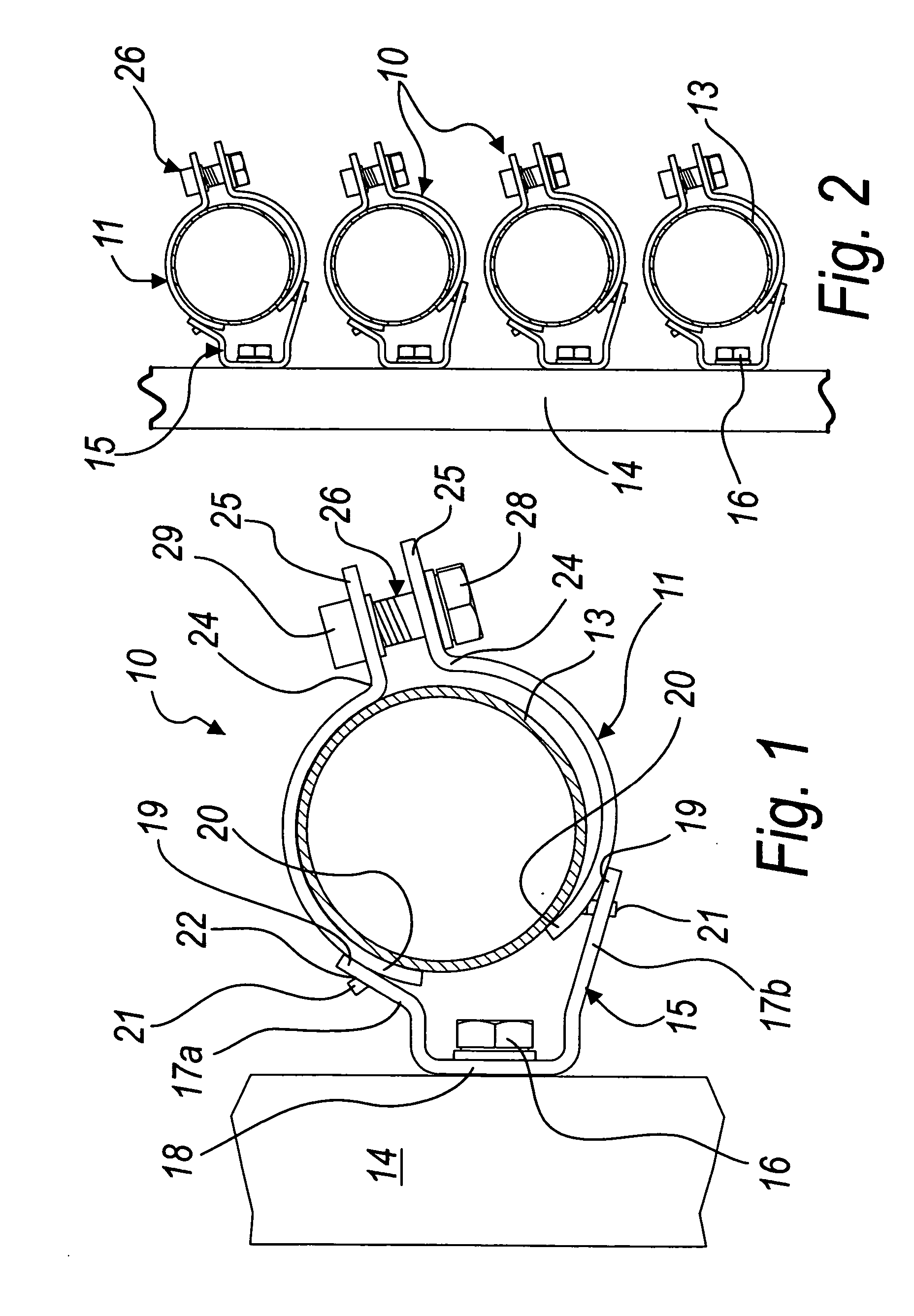
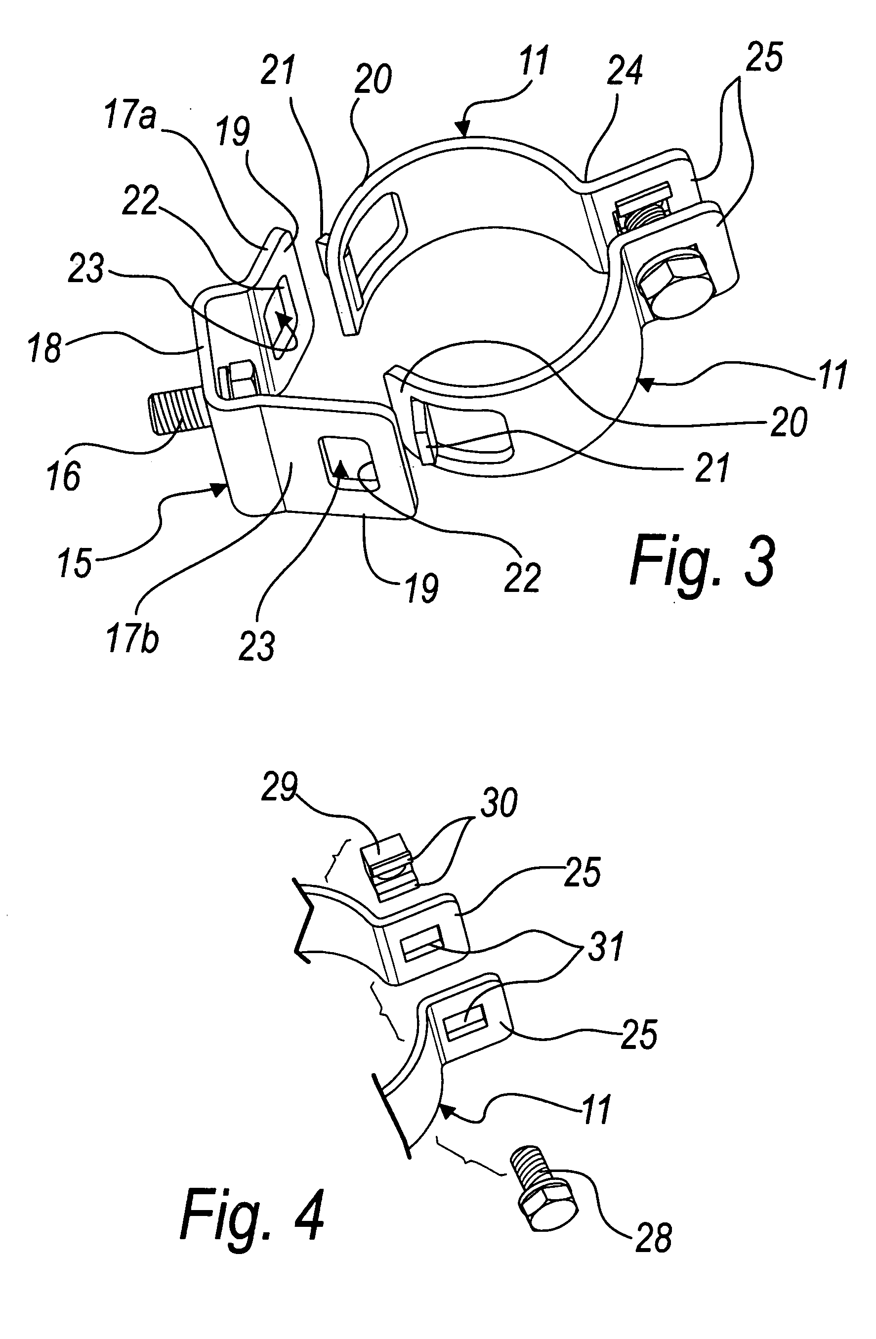
[0038] With reference to the figures, a device for fixing pipes to supporting structures according to the invention is generally designated by the reference numeral 10.

[0039] The fixing device 10 comprises two circular arched strips 11, which are substantially C-shaped and are mutually oppositely coupled so as to surround mutually opposite portions of the pipe 13 to be fixed to the supporting structure, such as an upright 14, which rests against a wall.

[0040] The device 10 further comprises a bracket 15 to be fixed to the supporting structure; in this embodiment, the bracket 15 is fixed to the upright 14 by means of a bolting assembly 16 (only the screw of the bolt is shown in the figures).

[0041] The bracket 15 has two mutually opposite cantilevered wings 17a and 17b; in particular, the cantilevered wings 17 protrude from the ends of a perforated base 18, through which the screw of the bolting assembly 16 is arranged.

[0042] Of these cantilevered wings, a first wing 17a is inclin...


PUM


Abstract

A device for fixing pipes to supporting structures, comprising two C-shaped circular strips mutually oppositely coupled so as to surround mutually opposite portions of a pipe to be fixed to the supporting structure, and a fixing bracket, which is provided with two mutually opposite cantilevered wings. Respective first ends of the circular strips are engaged on the facing portions of the free ends of the two cantilevered wings. Protruding teeth are provided on each of the first ends, arranged in abutment against a corresponding engagement portion provided on a respective cantilevered wing.

Description

[0001] The present invention relates to a device for fixing pipes to supporting structures. BACKGROUND OF THE INVENTION [0002] As it is known, in the production of industrial plants there is often the need to provide lines for conveying material that is useful for the most disparate applications, including the conveyance of supply or discharge water, the conveyance of compressed air, the conveyance of liquids for cooling, the conveyance of food liquids, the conveyance of powders and granules, et cetera. [0003] Of course, depending on the use, the materials of the pipes are the most suitable for the requirements; pipes made of plastics, galvanized steel, stainless steel and other disparate materials are typically used. [0004] These pipes must be fixed to the structures of the plant by virtue of adapted elements, which allow to secure each pipe in one point so as to be able to restrain it. [0005] The most widely used pipe fixing devices are divided substantially into two categories: a...

Claims


Application Information

Patent Timeline
Patent Type & Authority Applications(United States)
IPC IPC(8): F16L3/08
CPCF16L3/1066F16L3/221F16L3/127F16L3/1083
Inventor MORETTO, RENATO
Owner MORETTO SPA
Learn More