Multistage system for radiant energy flux transformation

a multi-stage energy flux and radiant energy technology, applied in the direction of instruments, lighting and heating apparatus, optical elements, etc., can solve the problems of limited energy collection ability of one-stage energy concentrators, limited shape and alignment tolerances of prior art design concepts, and poor boundary definition of concentrated beams projected on target areas. achieve the effect of increasing the efficiency of desired flux transformation

Inactive Publication Date: 2007-02-15
S V V TECH INNOVATIONS
View PDF23 Cites 35 Cited by
  • Summary
  • Abstract
  • Description
  • Claims
  • Application Information

AI Technical Summary

Benefits of technology

[0014] In accordance with the present invention, the prior art problems are solved by a multistage system for radiant energy flux transformation comprising a primary concentrating collector being a rear-focus reflector structure and an elongated secondary collector. The primary collector is formed by an array of slat-like reflective surfaces having longitudinal axes extending parallel to each other and reflecting the incident energy to a plurality of converging directions to form a common linear focal area. Each reflective surface is tilted away from the direction to the energy source at an angle preferably less than 45° so that the incident flux is reflected from it at an angle being greater than 45° and not greater than 90° to provide a rear disposition of the focal area formed by the primary collector. The secondary collector is disposed in energy receiving relation with at least one of reflective surfaces of the primary collector to intercept and redirect at least a part of radiant energy flux reflected from the primary collector so that the efficiency of desired flux transformation is increased.
[0015] According to one aspect of the invention, in a preferred embodiment, there is provided a multistage system for radiant energy flux transformation in which reflective surfaces of the primary collector are designed and positioned to minimize screening and shadowing on other reflective surfaces. The primary collector can also incorporate two or more symmetric segments facing toward each other.
[0016] According to another aspect of the invention, when it is applied to transforming and utilizing solar energy, the focal line of concentrated sun rays is situated below the primary reflector structure with the advantageous result that the secondary concentrating collector can be disposed in a close proximity to said focal line without shadowing the primary collector and without associated energy loss. The multistage system for radiant energy flux transformation can further incorporate a photovoltaic receiver.

Problems solved by technology

While parabolic mirrors are notably superior in concentration over the lenses, this prior art design concept has the limitation of requiring tight shape and alignment tolerances to keep the concentrated sunlight focused onto a narrow target area.
On the other hand, there is a limitation of energy collection ability of one-stage energy concentrators related to finite angle (one half degree) the sun subtends.
As a result, the concentrated beam projected on the target has poorly defined boundaries because they are formed by the rays mainly emanated from the edge portions of the solar disk.
One of the major problems of such past proposals is the inherent problem of partial shadowing the primary concentrator by the secondary and relative inaccessibility of the focal line which hampers the utility of the devices.
The known multi-reflection systems, such as those derived from Cassegrain telescope optics, have a further drawback that the entire flux reflected by the primary mirror is entirely redirected back by the secondary mirror resulting in a longer path of concentrated flux and decreased concentration efficiency.

Method used


Image

  • Multistage system for radiant energy flux transformation
  • Multistage system for radiant energy flux transformation
  • Multistage system for radiant energy flux transformation

Examples


Embodiment Construction

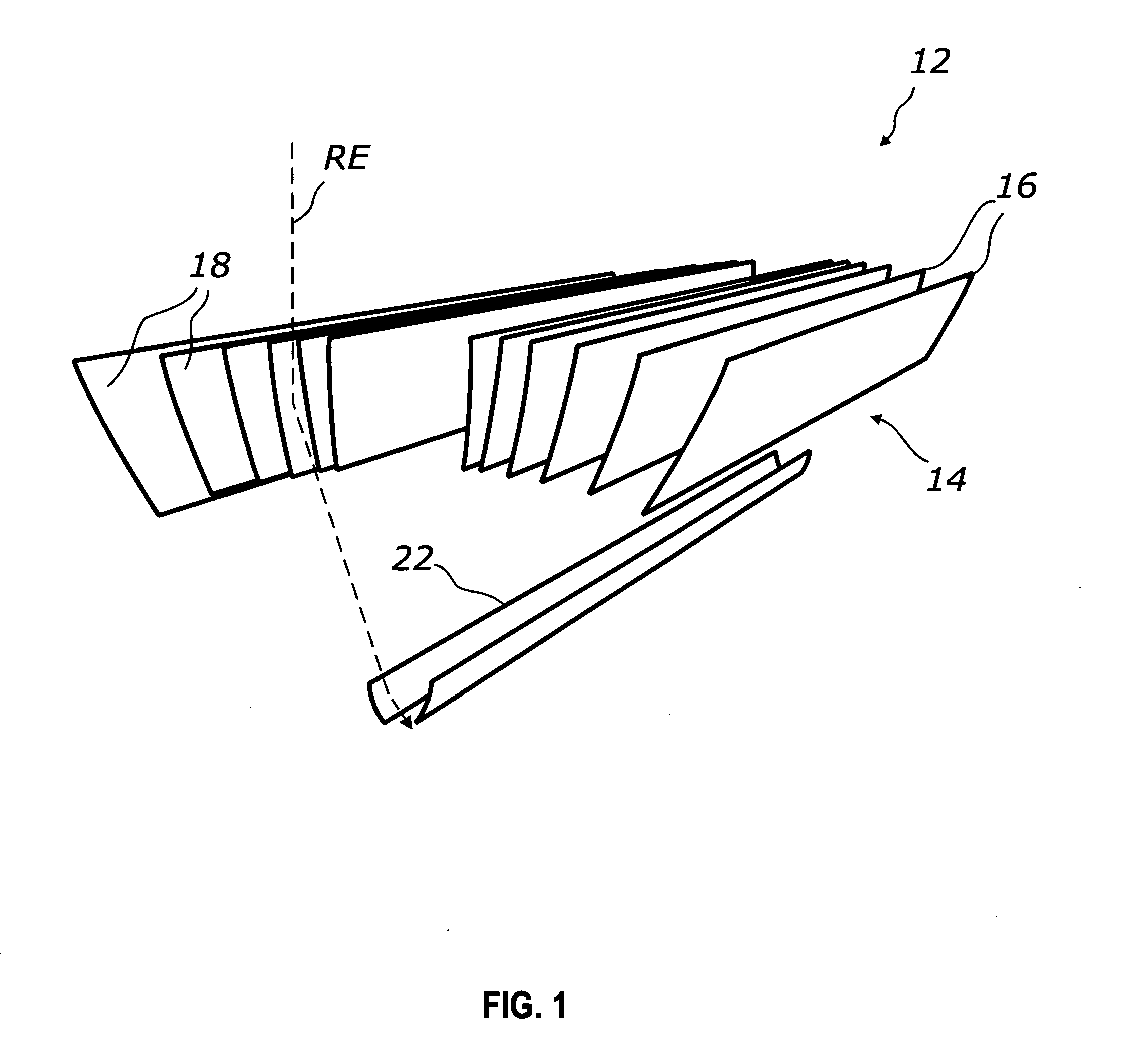
[0025] The embodiments of flux transformation systems selected for the purpose of illustrating the invention include a primary rear-focus concentrating flux collector and an elongated secondary flux collector.

[0026]FIG. 1 shows a perspective schematic view of a system 12 for concentrating and transforming radiant energy flux according to a preferred embodiment. System 12 includes a primary concentrating collector 14 comprising an array of cylindrical elongated reflectors 16 with longitudinal axes generally aligned parallel to a reference line (not shown), and an elongated secondary concentrating collector 22 extending parallel to reflectors 16. The array of reflectors 16 comprises two symmetric segments where reflectors 16 are spaced apart and positioned adjacent to each other.

[0027] Reflectors 16 are individually tilted and aligned in a stepped arrangement, so that primary collector 14 has a linear Venetian blind-like configuration with the front longitudinal edges of reflectors ...


PUM


Abstract

A radiant energy flux transformation system including a primary linear focus concentrating collector formed by a plurality of cylindrical slat-like reflectors and a secondary elongated collector is described. The reflectors of primary collector generally have concave or planar transversal profiles and are positioned in a stepped arrangement with longitudinal axes being parallel to each other and to the secondary collector. The reflectors are tilted away from the direction to the source of radiant energy at a range of angles being less than 45° to reflect and direct the incident energy flux to a common focal region located below the primary collector where the concentrated flux is intercepted and further transformed by the secondary collector. In addition to efficient concentrating radiant energy such as sunlight, the system can provide uniformity or a desired energy distribution in the concentrated flux.

Description

CROSS-REFERENCE TO RELATED APPLICATIONS [0001] This application is a continuation-in-part of application Ser. No. 10 / 339,123 filed Jan. 09, 2003, which is a continuation-in-part of application Ser. No. 10 / 026,121 Dec. 17, 2001, now U.S. Pat. No. 6,971,756.BACKGROUND OF THE INVENTION [0002] 1. Field of the Invention [0003] The present invention relates to a device for concentrating and transforming radiant energy with a multistage energy flux transformation system. In particular, this invention relates to linear focus solar energy concentrators. [0004] 2. Description of Prior Art [0005] It is well known that cylindrical parabolic mirrors and Fresnel lenses are used to concentrate the solar radiation which intensity is otherwise fairly low at the ground level for its direct use. While parabolic mirrors are notably superior in concentration over the lenses, this prior art design concept has the limitation of requiring tight shape and alignment tolerances to keep the concentrated sunlig...

Claims


Application Information

Patent Timeline
Patent Type & Authority Applications(United States)
IPC IPC(8): G02B5/10F24S23/70
CPCF24J2/10F24J2/18F24J2002/1095G02B17/006G02B19/0028G02B27/0983Y02E10/40G02B19/0042G02B19/0023G02B17/008F24S23/70F24S23/79F24S2023/878
Inventor VASYLYEV, SERGIY VICTOROVICHVASYLYEV, VIKTOR PETROVYCH
Owner S V V TECH INNOVATIONS
Why Eureka
Try Eureka