
Internal combustion engine

a combustion engine and internal combustion technology, applied in the direction of machines/engines, mechanical equipment, non-fuel substance addition to fuel, etc., can solve the problems of narrow operable area with stability, difficult control of ignition timing, and the need to separate the preparation of fuel with high ignitability and fuel with low ignitability

Inactive Publication Date: 2007-02-15
HONDA MOTOR CO LTD
View PDF8 Cites 107 Cited by
  • Summary
  • Abstract
  • Description
  • Claims
  • Application Information

AI Technical Summary

Benefits of technology

[0010] The present invention has an object to provide an internal combustion engine that solves the above described problems, uses a blended fuel consisting of hydrocarbon and alcohol, and can efficiently operate relative to a wide range of required load.
[0012] In the internal combustion engine according to the present invention, the first injector injects the hydrocarbon fuel, and the second injector injects the alcohol fuel, and thus jet quantities of the hydrocarbon fuel and the alcohol fuel can be independently controlled according to a required load of the internal combustion engine. Thus, according to the internal combustion engine of the present invention, jet ratios of the hydrocarbon fuel and the alcohol fuel can be easily adjusted, thereby allowing control to an optimum combustion mode and an efficient operation relative to a wide range of required load.
[0014] In the internal combustion engine according to the present invention, the combustion chamber may comprise an ignition plug so as to be switchable between self compression ignition and forced ignition with the ignition plug. In this case, the internal combustion engine is controlled to an optimum combustion mode according to a required load. Specifically, when the compression ignition is possible, the ratio of the alcohol fuel is properly maintained, and ignition timing is properly controlled. When the forced ignition with the ignition plug is performed, the ratio of the alcohol fuel is controlled so as to prevent knocking even when ignition timing is set to provide maximum efficiency.
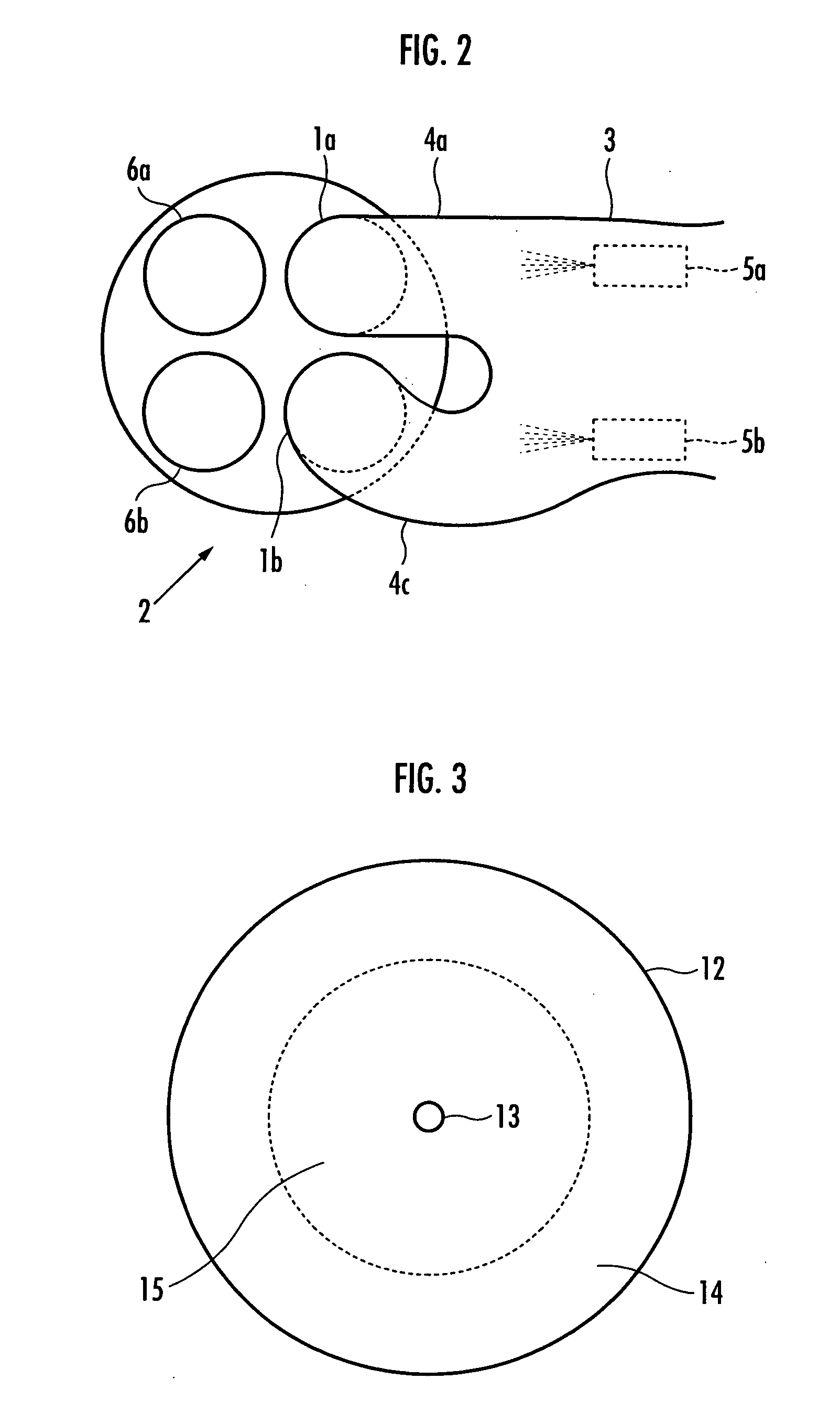
[0016] The first and second intake ports can form octane number distribution in the combustion chamber by the fuels guided to the combustion chamber so that an area with a low octane number is formed in the inner peripheral portion of the combustion chamber and an area with a high octane number is formed in the outer peripheral portion of the combustion chamber, thereby preventing knocking at high load. The first and second intake ports are used together with the adjustment of the jet ratios of the alcohol fuel and the hydrocarbon fuel, thereby further reliably preventing knocking at high load.

Problems solved by technology

However, the compression ignition internal combustion engine has a problem that control of ignition timing is difficult unlike an internal combustion engine of a spark ignition type, and an operable area with stability is narrow.
More specifically, this problem is that using a fuel with high ignitability may easily cause knocking when a required load of the engine is increased, and using a fuel with low ignitability may easily cause misfire when the required load of the engine is reduced.
In this technique, however, the fuel with high ignitability and the fuel with low ignitability need to be separately prepared and housed.
However, partial oxidation of hydrocarbon such as the gas oil to generate formaldehyde requires a long-time reaction at high temperature.
However, when the blended fuel is supplied to a cylinder as a single fuel like gasoline and ignited by spark ignition, a sufficiently high efficiency cannot be obtained.

Method used


Image

  • Internal combustion engine
  • Internal combustion engine
  • Internal combustion engine

Examples


Embodiment Construction

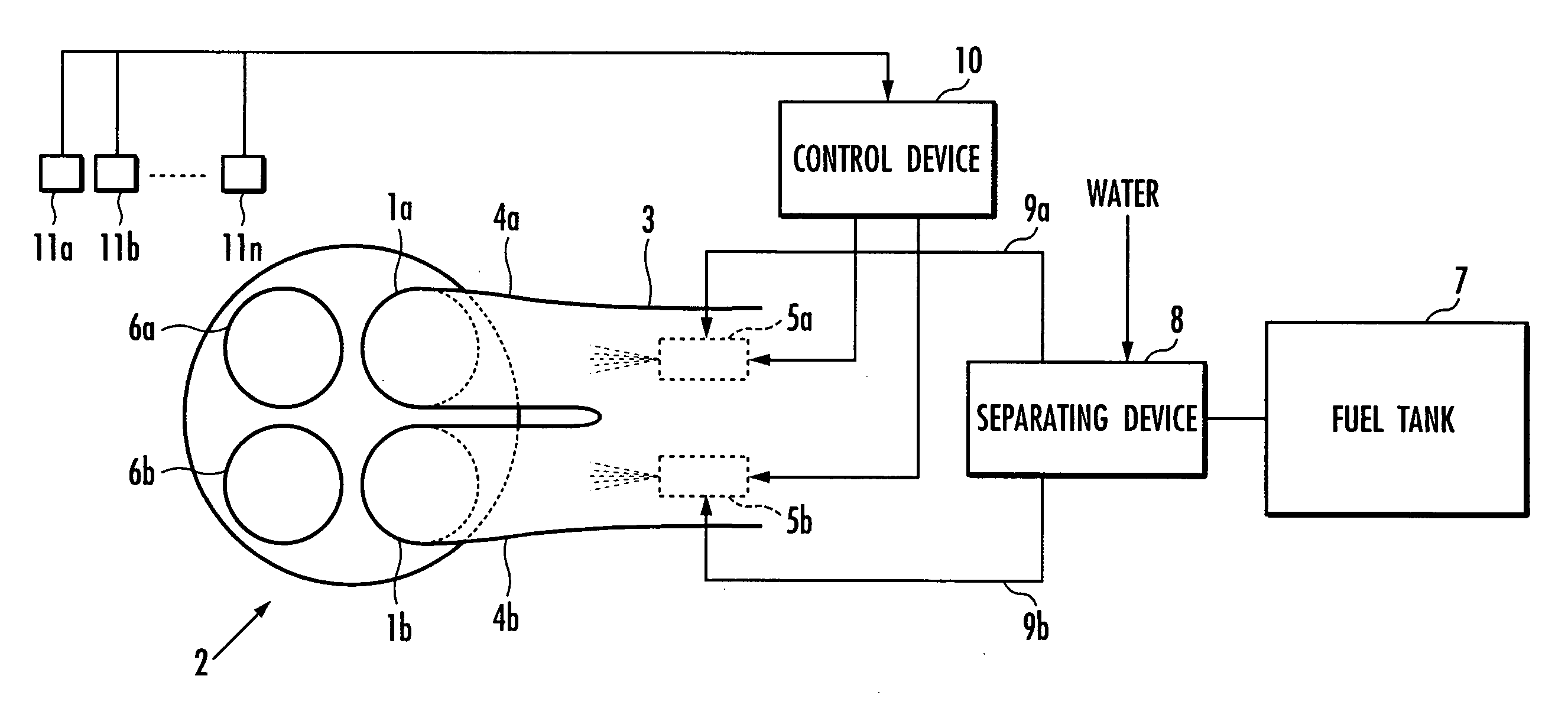
[0022] Now, an embodiment of the present invention will be described in more detail with reference to the accompanying drawings. FIG. 1 is a system configuration diagram showing an exemplary configuration of an internal combustion engine according to the present invention, FIG. 2 shows a variation of in take ports in FIG. 1, and FIG. 3 is an illustrative sectional view of a cylinder comprising the intake ports in FIG. 2.

[0023] As shown in FIG. 1, the internal combustion engine according to the embodiment comprises a cylinder head 2 comprising two intake valves 1a and 1b, and an intake pipe 3 connected to the intake valves 1a and 1b. The cylinder head 2 forms atop of an unshown cylinder, and the cylinder is provided with an ignition plug.

[0024] A tip of the intake pipe 3 is divided into two parts to form an intake port 4a connected to the intake valve 1a and an intake port 4b connected to the intake valve 1b. The intake ports 4a and 4b both are of a straight type, and an injector 5...


PUM


Abstract

There is provided an internal combustion engine that uses a blended fuel consisting of hydrocarbon and alcohol, and can efficiently operate relative to a wide range of required load. The internal combustion engine includes: intake ports 4a and 4b and two injectors 5a and 5b. The injectors include a first injector 5a that injects a hydrocarbon fuel and a second injector 5b that injects an alcohol fuel. An optimum combustion mode is selected according to an operation state, and the ratio of the alcohol is properly adjusted according to the combustion mode. The intake ports includes a first intake port 4a that guides the hydrocarbon fuel to an inner peripheral portion of a combustion chamber, and a second intake port 4c that guides the alcohol fuel to an outer peripheral portion of the combustion chamber to control octane number distribution in a cylinder. The internal combustion engine further includes separating means 8 for adding water to a blended fuel consisting of alcohol and hydrocarbon to separate into the alcohol fuel consisting of the alcohol and the water and the hydrocarbon fuel.

Description

BACKGROUND OF THE INVENTION [0001] 1. Field of the Invention [0002] The present invention relates to an internal combustion engine that uses a blended fuel consisting of hydrocarbon and alcohol. [0003] 2. Description of the Related Art [0004] In recent years, compression ignition internal combustion engines such as homogeneous charge compression ignition internal combustion engines have been studied in order to increase gas mileage of an internal combustion engine and reduce emissions. The compression ignition internal combustion engine introduces oxygen-containing gas and fuel capable of compression self-ignition into a cylinder for compression and self-ignition. [0005] However, the compression ignition internal combustion engine has a problem that control of ignition timing is difficult unlike an internal combustion engine of a spark ignition type, and an operable area with stability is narrow. More specifically, this problem is that using a fuel with high ignitability may easily ...

Claims


Application Information

Patent Timeline
IPC IPC(8): F02M51/00F02B15/00F02B13/00
CPCF02B47/02F02D19/081F02M25/0228F02M43/04F02D19/084Y02T10/36F02D19/0663F02D19/0671F02D19/0692Y02T10/121Y02T10/12Y02T10/30
Inventor KAMIO, JUNICHIKIYOHIRO, YUKIHIKOBANNAI, TAKASHI
Owner HONDA MOTOR CO LTD
Learn More