
Arrangement for coupling pallets of a travelator

a technology for travelators and pallets, which is applied in the direction of escalators, transportation and packaging, conveyors, etc., can solve the problems of complicated coupling arrangements, long installation times, and slow implementation of coupling solutions and the associated adjustments, so as to achieve short installation, maintenance and repair times, and easy and fast installation

Inactive Publication Date: 2007-02-08
KONE CORP
View PDF19 Cites 9 Cited by
  • Summary
  • Abstract
  • Description
  • Claims
  • Application Information

AI Technical Summary

Benefits of technology

The present invention provides an arrangement for coupling pallets in a conveying device, such as a travelator, moving ramp or escalator, which is economical and easy to install and maintain. The pallet is connected to a chain functioning as a drive element moving the pallets, making the installation and repair times short. The coupling solution is simple and reliable, safe, and requires no special tools. The coupling element is of small size and light weight, not taking up much space around its path and not straining the travelator structures by its weight. The pallet can be easily fastened to the chain during installation, and during maintenance or repair the pallet can be easily released from the chain and secured to it again. The connection is easy to make and release, installation and maintenance work require less time.

Problems solved by technology

In known solutions, the coupling arrangements are complicated and often also require the use of special tools for the coupling to be successfully performed in the desired manner.
These known coupling solutions and the associated adjustments are slow and complicated to implement, which is why the installation times are very long, especially when long travelators are to be installed.
This is expensive and otherwise undesirable.
In addition, maintenance and repair operations take a longer time because the release and re-mounting of known coupling elements is a slow process.
Coupling elements of a larger size, which take up space around their path of motion and add to the weight of the structures present further problems.
An additional problem in known coupling elements is the chain serving as a drive element, which has to be of a special construction due to the coupling.
Such a chain, which is specific only to a given application, is generally expensive and may be difficult to obtain in urgent cases of repair.

Method used


Image

  • Arrangement for coupling pallets of a travelator
  • Arrangement for coupling pallets of a travelator
  • Arrangement for coupling pallets of a travelator

Examples


Embodiment Construction

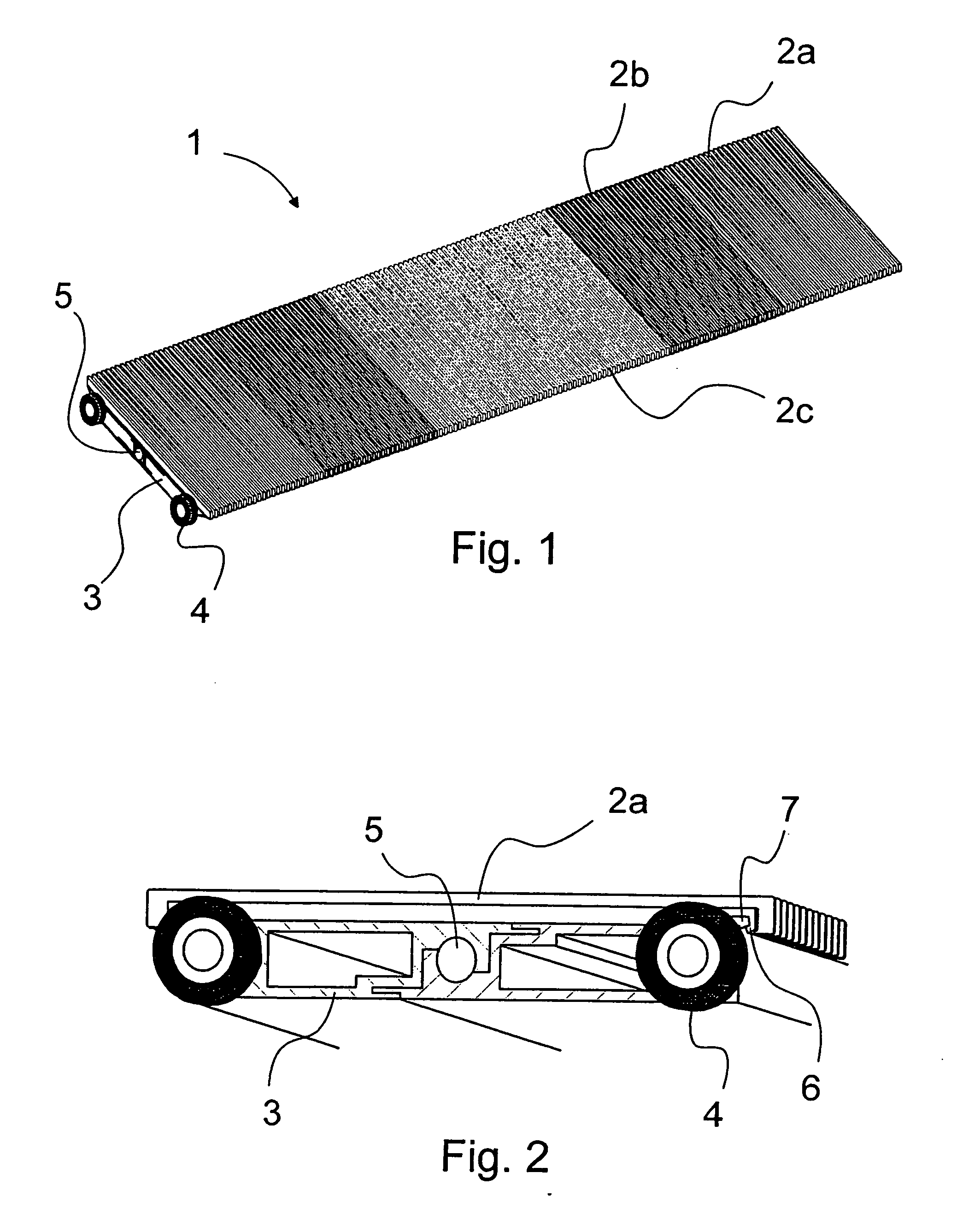
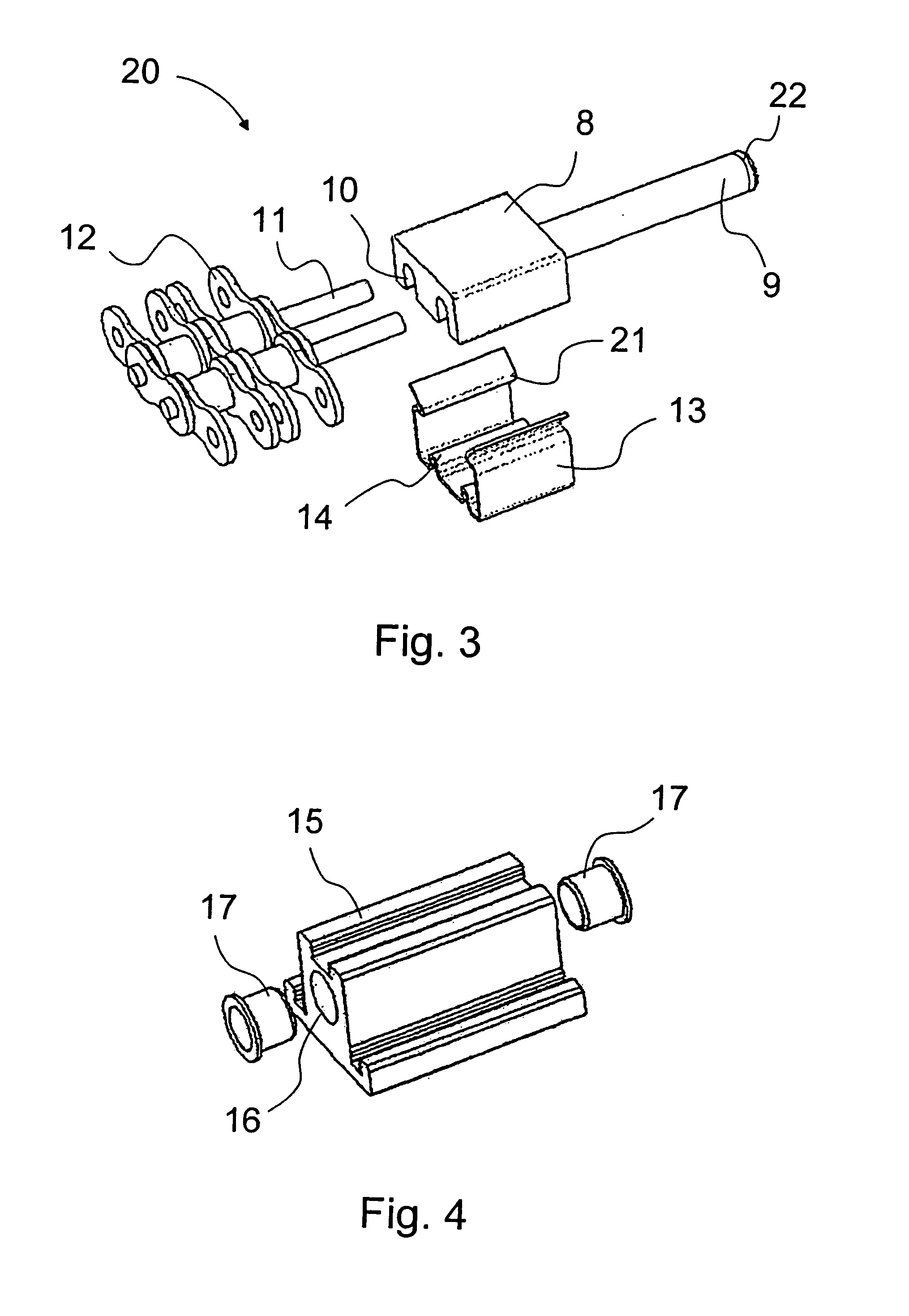
[0015] Referring to FIG. 1, there is shown a pallet structure 1 comprising a pallet body 3, which has preferably been produced by extruding a suitable profile from aluminum or some other appropriate metal or metal alloy. During manufacture of the profile, a given profile is extruded in bars of a length suited for manufacture, transport or other purposes. Later during manufacture of the pallet, parts of a length exactly suited for the purpose are cut from these profiled bars. Thus, the same profile can easily be used for pallets of different lengths, which makes it easy to vary the width of the conveyor track of the travelator. Secured to the pallet body 3 are wheels 4 at each end of the pallet and likewise at least at one end a fastening element 20 (see for example FIGS. 3 and 5), by which the pallet 1 is coupled to an endless chain, toothed belt, rope or equivalent actuating element serving to move the pallets. The fastening element 20 is secured e.g. to a mounting hole 5 (FIGS. 1 ...


PUM


Abstract

An arrangement for coupling a pallet in a conveying device includes a pallet having wheels and forming a part of a transport track of the conveying device, and a drive element. A coupling piece is adapted to be connected to the pallet and a fastening parties connects the drive element to the coupling piece.

Description

CROSS-REFERENCE TO RELATED APPLICATIONS [0001] This application is a continuation of International Application No. PCT / FI2005 / 000007 filed Jan. 5, 2005, designating the United States and claiming priority from application Ser. No. FI20040157 filed in Finland on Feb. 2, 2004, the disclosures of both foregoing applications being incorporated herein by reference.BACKGROUND OF THE INVENTION [0002] The present invention relates to an arrangement for coupling pallets of a travelator or equivalent. [0003] Like escalators, travelators are conveying devices used to move people and goods. They differ from escalators e.g. in that they often work in a substantially horizontal position or in a position slightly inclined relative to their direction of motion, so that successive steps, i.e. pallets, form a substantially even and rectilinear transport track instead of stair-like steps as in escalators. Travelators are also referred to as moving sidewalks and autowalks. [0004] In known travelators, ...

Claims


Application Information

Patent Timeline
Patent Type & Authority Applications(United States)
IPC IPC(8): B66B23/12B65G17/42B66B23/10
CPCB66B23/10B65G17/42
Inventor AULANKO, ESKOMUSTALAHTI, JORMAOSSENDORF, MARC
Owner KONE CORP
Learn More