
Precision positioning and fastening system

a technology of positioning and fastening, applied in the direction of locking fasteners, bolts, light support devices, etc., can solve the problems of time-consuming and labor-intensive removal of dowels, axial force, and inability to meet the requirements of the application

Active Publication Date: 2007-02-01
MODERN IND
View PDF14 Cites 6 Cited by
  • Summary
  • Abstract
  • Description
  • Claims
  • Application Information

AI Technical Summary

Benefits of technology

"The present invention is a precision fastening system that allows for the secure and quick connection and disconnection of articles to a base. The system includes a locator with a retention head and a cylindrical body portion, and fastening means. The locator is designed to fit snugly into the article and the base, with the fastening means securely engaging the article to the base. The system is easy to use, cost-effective, and provides a quick connect / disconnect. It overcomes the limitations of current devices and allows for quick connect / disconnect while maintaining precise positioning."

Problems solved by technology

Dowel pins and other fasteners are adequate for some applications but are not without their limitations.
Dowel pins, for example, require application of axial force and removing the dowels can be time consuming.
If thread advancement is forced, galling of the holes and stripping of threads can occur.
Alternatively, or in addition, damage to the shoulder of the bolt can occur as it is pushed and rotated into the mis-aligned opening.
However, such means of locating / attaching can be costly to machine onto both items and certainly, does not provide a form of quick connect / disconnect.
One of the main problems with this system is that resulting binding can make it difficult to insert and remove this system making its use cumbersome and time consuming.

Method used


Image

  • Precision positioning and fastening system
  • Precision positioning and fastening system
  • Precision positioning and fastening system

Examples


first embodiment

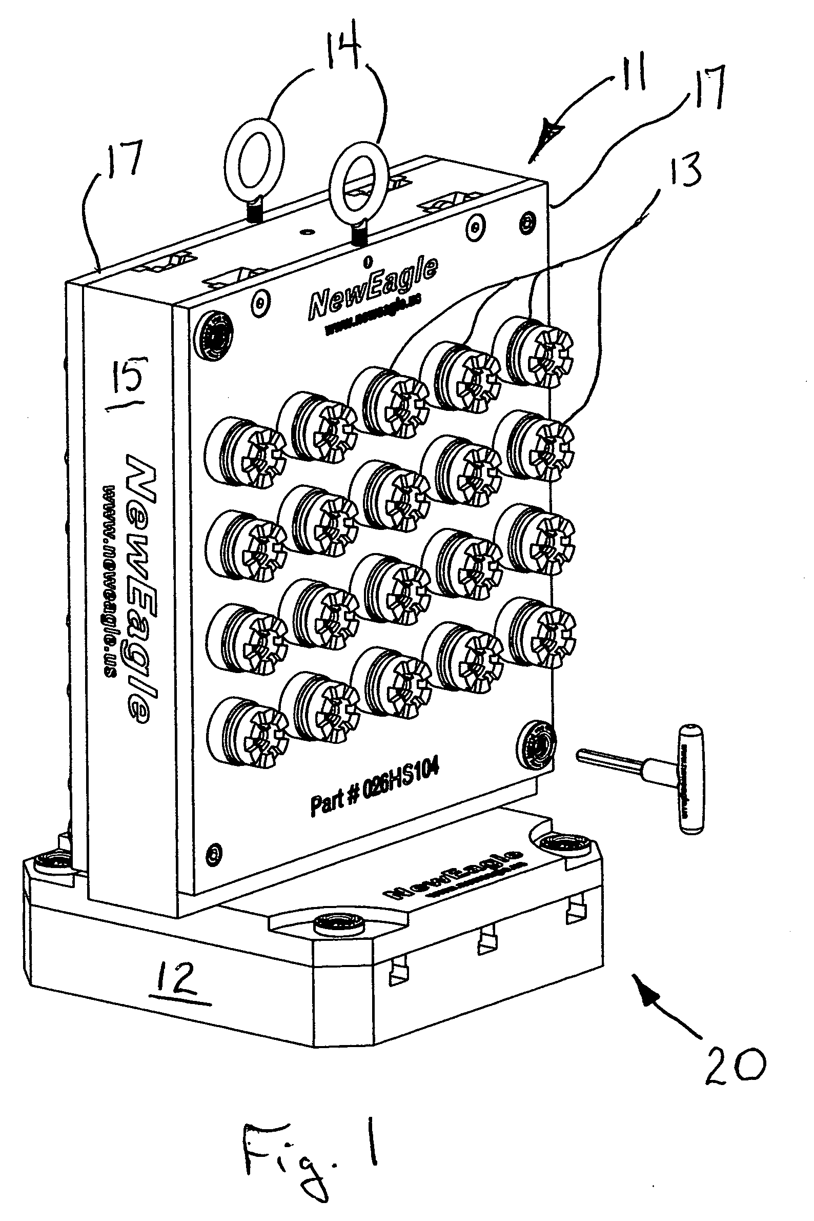
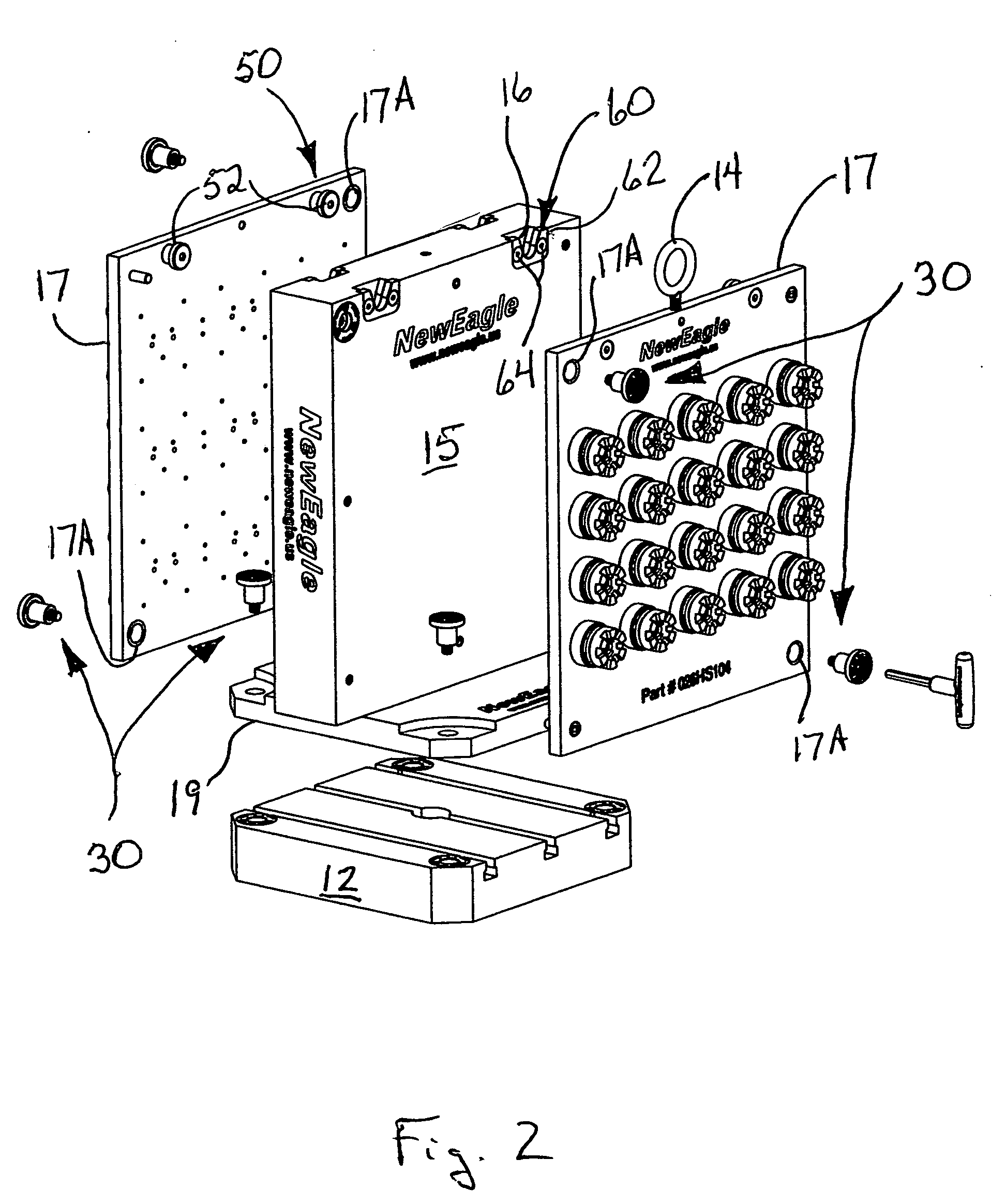
[0035] the locating and fastening system of the present invention is depicted in FIGS. 1 and 2 generally at 20. The locating and fastening system 20 of the present invention includes locator / fasteners 30 and a hanger system 50. As depicted in FIGS. 1 and 2, locating and fastening system 20 is used with a workholding chassis or tombstone 11 has secured thereto a number of workpieces 13 for performing machining operations thereon. Tombstone 11 includes a base 15 and two sub-base plates 17 from which workpieces 13 are suspended. Each sub-base plate 17 has a plurality of throughbores with a first set of center-lines 17A. Base 11 has flange 19 extending from either side which is attached to mounting plate 12. Flange 19 can be formed as a separate member and attached to base 11 or may be formed integrally therewith. Eyelets 14 are provided to enable sub-base plates 17 to be lifted and placed upon base 11. Locator / fasteners 30 can be used to fix flange 19 of base 11 to mounting plate 12.

[0...

second embodiment

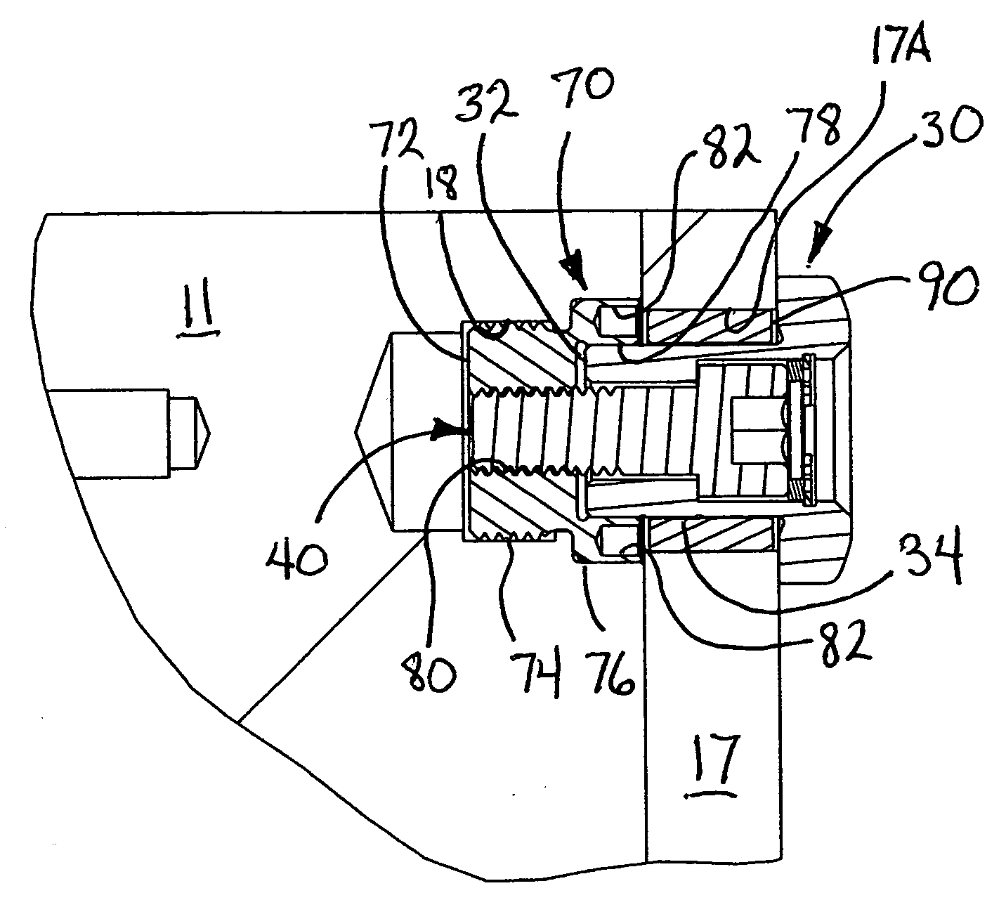
[0040] receiver is shown in FIGS. 5A, 5B generally at 70′. In this embodiment, rather than having integral threads on cylindrical body portion 72′, separate threaded fasteners 21′ engage through holes 75′ in head portion 76′ to secure it in opening in base 11′. FIG. 5B depicts an important feature of each of these receivers and locator fasteners. As seen there, lead end 35 of locator 32 is formed with an angular surface 82′. This angular surface 82′ may take the form of a chamfer or radiused surface. A complimentarily shaped surface 79′ is formed in the precision-machined opening 78′ in head portion 76′. These complementary surfaces enable the locator 32 to adjust for mis-alignment between the base 11 and sub-plate 17 which produces mis-alignment between the receiver 70′ and the locator / fastener 30. The combination of these cooperating angular surfaces 79′ and 82′ and the floating of fastener 40 within the throughbore 38, enable these misalignment difficulties to be overcome.

third embodiment

[0041]FIG. 6 shows yet receiver shown generally at 70″. This receiver 70″ is installed on the opposite side of base 15″ using a press fit. Obviously, body 72″ could be threaded or separate fasteners could be employed; however, since fastener 40 will pull the receiver 72″ against the rear portion of sub-base plate 17″, these additional fastening means are unnecessary.


PUM


Abstract

A locator / fastener has a first outer member with a precision-machined external body portion, a retention head protruding from a first end, and a multi-diameter throughbore. A fastener, which may take the form of a cap screw, floats in the throughbore of the locator with the threaded portion protruding from a second end of the locator. A receiver has an internal precision-machined surface which contacts the precision-machined body portion of the locator and a threaded bore which receives the protruding fastener. By separating the locating and fastening functions, a quick connect disconnect device is created which does not bind or gall. A hangar system allows a sub-base plate to be attached to a base using the locator-fastener disclosed herein.

Description

[0001] Applicant claims benefit of provisional patent application 60 / 605,057 filed Aug. 27, 2004.BACKGROUND AND SUMMARY OF THE INVENTION [0002] The present invention is directed to the field of precision fastening. More particularly, the present invention is directed to a precision locating and fastening system particularly useful in securing work pieces to a work holder for machining operations. [0003] Currently, devices for locating and anchoring articles include dowel pins, a variety of fasteners including shoulder bolts, key ways including T-keys and T-bolts, for example. Dowel pins and other fasteners are adequate for some applications but are not without their limitations. Firstly, when quick connect / disconnect is desired, dowel pins and threaded fasteners typically are found wanting. Dowel pins, for example, require application of axial force and removing the dowels can be time consuming. Typically, dowel pins are used for locating an article and other forms of fasteners are ...

Claims


Application Information

Patent Timeline
Patent Type & Authority Applications(United States)
IPC IPC(8): F16B21/18
CPCF16B5/0208F16B5/025F16B21/18F16B37/14Y10T403/7015F16B39/08Y10S269/902Y10T403/1624F16B37/145
Inventor DURFEE, DAVID L. JR.
Owner MODERN IND
Learn More