
Image capturing device having multiple optical systems

a technology of optical system and image capturing device, which is applied in the field of image capturing device, can solve the problems of increasing the size of digital camera, inconvenient for a user of compact digital camera, and no reference discloses the switching of optical system, so as to achieve the effect of reducing power consumption

Inactive Publication Date: 2007-02-01
INTELLECTUAL VENTURES FUND 83 LLC
View PDF9 Cites 135 Cited by
  • Summary
  • Abstract
  • Description
  • Claims
  • Application Information

AI Technical Summary

Benefits of technology

[0012] The present invention advantageously provides an image capturing device having multiple optical systems in which multiple image capturing elements are effectively driven so as to reduce power consumption.
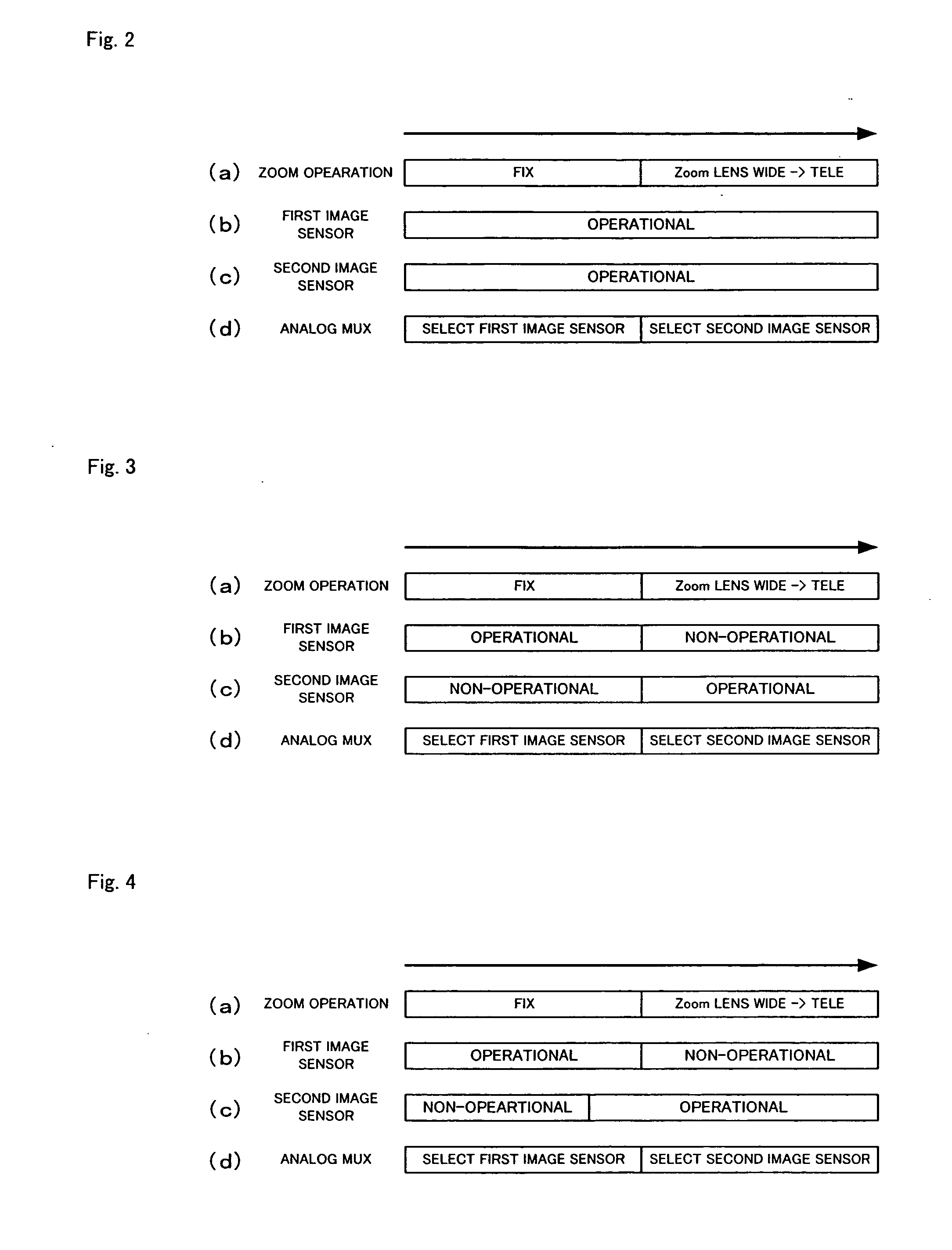
[0016] According to the present invention, in an image capturing device having multiple image capturing optical systems in which an image signal from one of the optical systems is selectively output, the image capturing element that is not selected is set to a non-operational state so that power consumption is reduced.

Problems solved by technology

Unfortunately, providing a large zoom range lens, without sacrificing the quality of the captured images, increases the size of the digital camera.
With higher-cost cameras, such as single lens reflex cameras, these problems are sometimes addressed by using multiple, interchangeable zoom lenses, such as a 28-70 mm zoom and a 70-210 mm zoom.
Such an option, however, is inconvenient for a user of a compact digital camera.
Thus, none of these references discloses how the optical system is switched among the multiple optical systems.
However, a structure for driving the image capturing elements using drivers provided in correspondence to the image capturing elements requires high power, and, therefore, may shorten a drive time of the digital camera using a battery.

Method used


Image

  • Image capturing device having multiple optical systems
  • Image capturing device having multiple optical systems
  • Image capturing device having multiple optical systems

Examples


Embodiment Construction

[0046] A preferred embodiment of the present invention will now be described referring to the drawings.

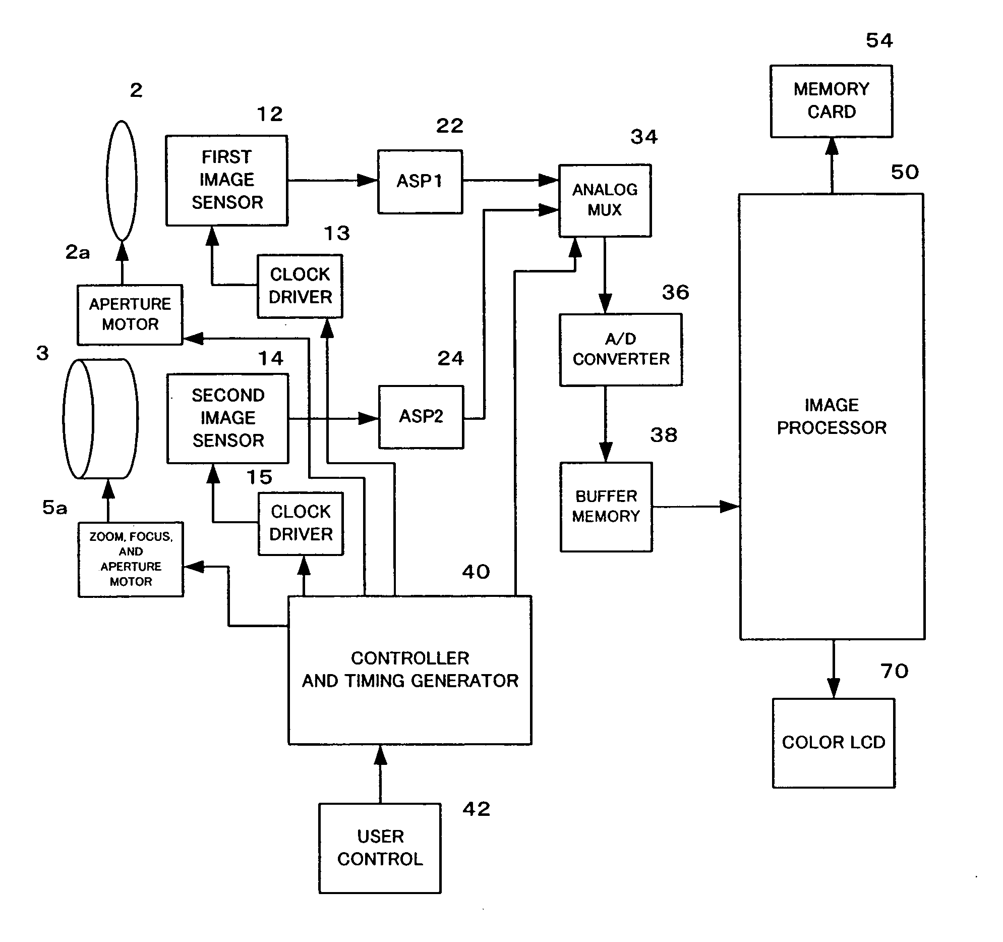
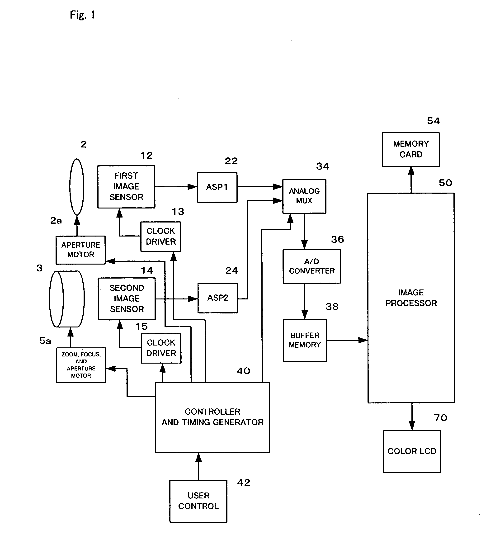
[0047]FIG. 1 is a block diagram showing a basic structure of a digital camera according to a preferred embodiment of the present invention. The digital camera is a portable camera which is driven by a battery. The digital camera produces a still digital image which is stored in a removable memory card 54. The digital camera may produce a motion digital image in addition to or in place of the still image. The motion digital image is similarly stored in the memory card 54.

[0048] The digital camera comprises an image capturing assembly which includes a fixed focal length lens 2 which forms an image of a scene on a first image sensor 12 and a zoom lens 3 which forms an image of the scene on a second image sensor 14. The image capturing assembly provides a first image output from the first image sensor 12 and a second image output from the second image sensor 14. The image sensors 12 ...


PUM


Abstract

In a digital camera having multiple optical systems, multiple image capturing elements are effectively driven to reduce power consumption. A digital camera has a first image capturing optical system having a lens and a first image sensor and a second image capturing optical system having a lens and a second image sensor. A controller and timing generator selects the image signal from the first image capturing optical system while controlling an operation or power of the second image sensor and a clock driver to be OFF when the zoom position falls within a first zoom range. When the zoom position falls within a second zoom range, the image signal from the second image capturing optical system is selected while an operation or power of the first image sensor and a clock driver is controlled to be OFF. An operation or power of the image capturing optical system which is not selected is stopped so that power consumption is reduced.

Description

FIELD OF THE INVENTION [0001] The present invention relates to an image capturing device such as a digital camera and, more particularly, to an image capturing device having multiple optical systems for capturing an image of a scene. BACKGROUND OF THE INVENTION [0002] Currently, many digital cameras have a zoom lens and a single image sensor to capture still and motion images. The captured images are then digitally processed to produce digital image files, which are stored in a memory in the digital camera. The digital image files can then be transferred to a computer and displayed, or transferred to a printer and printed. [0003] Small camera size and a large optical zoom range are very important features of digital cameras. Users prefer to have a large zoom range rather than a limited zoom range. Unfortunately, providing a large zoom range lens, without sacrificing the quality of the captured images, increases the size of the digital camera. With higher-cost cameras, such as single...

Claims


Application Information

Patent Timeline
IPC IPC(8): G02B13/16
CPCH04N5/23293H04N5/23296H04N5/23241H04N5/2254G02B7/102H04N23/651H04N23/63H04N23/69
Inventor NAKAMURA, HIDEOHORIGOME, GAKUJIKOBAYASHI, MASAOKURATA, KAZUYASU
Owner INTELLECTUAL VENTURES FUND 83 LLC
Learn More