Open ended interlocking block system

Inactive Publication Date: 2007-02-01
HAENER JUAN
View PDF16 Cites 6 Cited by
  • Summary
  • Abstract
  • Description
  • Claims
  • Application Information

AI Technical Summary

Benefits of technology

[0010] The device herein disclosed provides concrete blocks for construction of walls using a single block design or two or more block designs that provide for an especially easy method to construct a sturdy wall. The device in all modes employs an “H” shaped first block design which incorporates a number of interlocking features that improve strength and stability of walls and structures. The block also incorporates a double open-end design which eliminates the endwalls required by conventional rectangular blocks. This provision of open endwalls allows for improved vertical metal reinforcing rod engagement between layers of blocks forming the wall without the need to lift and slowly lower the heavy blocks on the upright metal rods. Instead, the blocks are simply angled to allow the open ends to slide around the upright metal rods, thereby reducing the time and effort and number of laborers required to build a wall of great strength. The block may then be locked into place with cooperating projections and receiving cavities of the other adjacent and lower interlocking blocks with the re-bar in the proper location in the block cavity.
[0011] Further, the double open-end design allows for improved grout or mortar flow around reinforcing steel and block cavity filling, thereby allowing a higher number of levels or layers of the blocks to be operatively engaged with each other and subsequently internally grouted from above through formed channels for the mortar or grout to flow.
[0012] In all embodiments of the device, be it the single block system or employing a second block for aesthetic purposes, the tapered vertical interlocking pins and cooperative engagements for the pins in adjacent overhead blocks allow for tolerances during the building process which provide for longitudinal adjustment of up to ⅛ inch per block. This provides a means adjustment of the final length of the wall as-built and provides a remedy in case of any errors in placement of a block in a layer forming the wall.

Problems solved by technology

Additionally, the workers can be of minimal skill and education since the blocks interlock with each other, and in the simplest mode of the device there is only one block style used.

Method used


Image

  • Open ended interlocking block system
  • Open ended interlocking block system
  • Open ended interlocking block system

Examples


Embodiment Construction

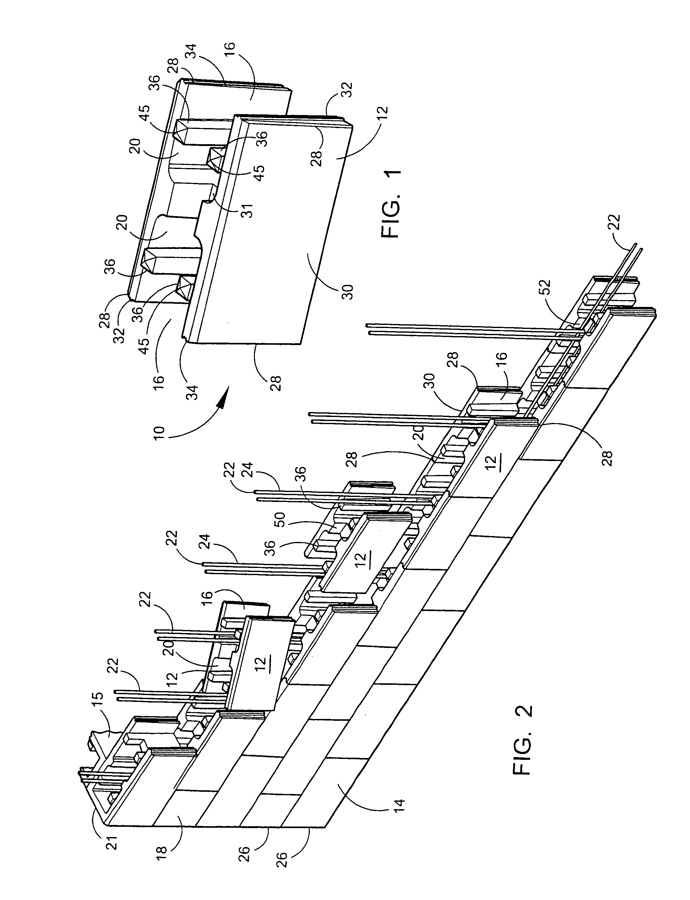
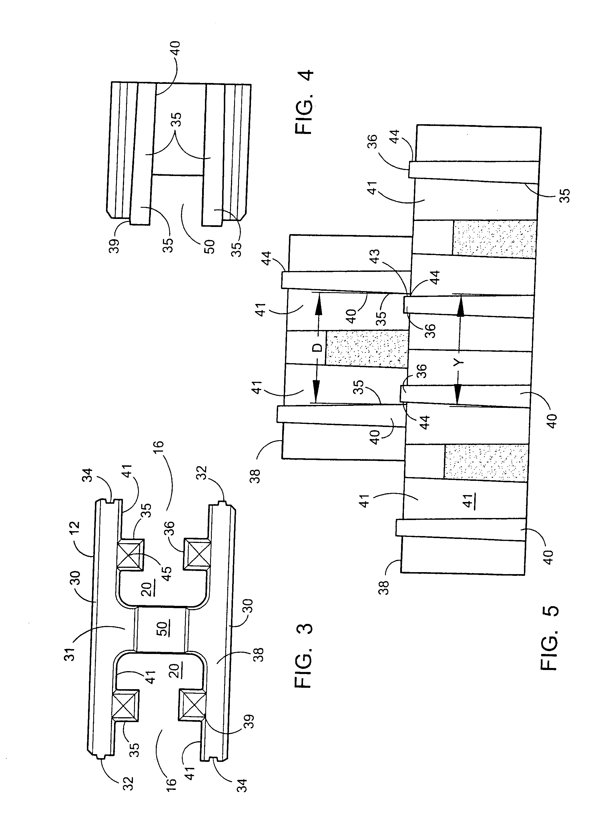
[0031] As shown in FIGS. 1-8, the device employs a one block building system providing for building of a wall structure formed of single interlocking block style. The device 10 provides great utility in the building of walls with interlocking blocks 12 as shown in FIGS. 2 and 6, using a generally “H” shaped primary blocks 12 which can be employed as the sole block used in building a wall 14. The block 12 is formed in this shape by a pair of parallel sidewalls 30 extending from a middle portion 31. The primary block 12 will allow for the building of straight walls or walls with corners engaged to traverse walls 15 where the primary block 12 would be employed as a corner block anchoring the walls perpendicular to each other.

[0032] When employed as a one block method or system, the primary block 12, on a retaining wall can have its opposing open ends 16, at both termination points at the sides of the wall, filled with mortar or concrete or simply left open and filled with adjacent soi...


PUM


Abstract

An interlocking block system building system for block walls which employs an “H” shaped open ended block to build any size walled structure. The device features a first block having a center portion connecting and two parallel sidewalls with two open ends opposite the endwalls. A plurality of interlocking tabs projecting from the top surface of the blocks engage with receptors in blocks stacked above. Projections and recesses formed on the distal edges of the blocks are adapted to engage with projections and recesses formed on the endwalls of adjacent blocks in a wall. The distal edge engagements may be translated to allow for adjustment of block spacing and ultimate wall size.

Description

BACKGROUND OF THE INVENTION [0001] 1. Field of the Invention [0002] The present invention relates to blocks which are conventionally employed to build privacy and retaining walls. More particularly, the device herein disclosed relates to a block system which allows the user to employ only two types of block to build any wall and optionally three types. The system employs a full sized block having a novel “H” shape. An entire wall may be formed of this single block. [0003] The unique “H” shaped block and “C” shaped block allow the user to build a wall with a high degree of sheer strength through the provision of projecting pins which engage with overhead blocks in the formed wall. Additional strength in the formed wall may be provided through interweaving vertical metal reinforcing bars which communicate through the levels of engaged blocks. When used in combination with such reinforcing bars, the device and method herein disclosed yields great utility by allowing the reinforcing bar...

Claims


Application Information

Patent Timeline
IPC IPC(8): E04B1/00E04B5/00
CPCE04B2/54E04B2002/0226E04B2002/0215E04B2002/0206
Inventor HAENER, JUAN
Owner HAENER JUAN
Why Eureka
Try Eureka