Portable external cell phone antenna

a cell phone antenna and external technology, applied in the direction of separate antenna unit combinations, radiating element structural forms, substation equipment, etc., can solve the problems of inconvenient operation, inconvenient use, and inconvenient use, etc., to enhance cell phone operation and enhance cell phone operation

Inactive Publication Date: 2007-01-18
BRUCEMARV
View PDF6 Cites 4 Cited by
  • Summary
  • Abstract
  • Description
  • Claims
  • Application Information

AI Technical Summary

Problems solved by technology

This system provided very highly reliable communication, but was too expensive to operate, the hand held devices were too large and expensive, and the two systems, Iridium and Globalstar filed for bankruptcy.
The other system, utilizing small hand held devices that transmitted to a local antenna tower, outperformed the satellite systems in terms of size, cost and versatility.
The competition between the various suppliers of cell phones has resulted in cell phones becoming smaller and smaller.
This trend has resulted in temperatures inside some cell phones becoming high enough to overheat the cell phone batteries, which have been reported exploding.
However, there are no portable antennas being offered for sale to significantly improve the performance of the cell phone of the average user that operate without the need for such a metallic surface.
However, until now, there are no practical portable antennas that provide significant improvement in cell phone reception.
If a secure link to the tower cannot be achieved, the call is lost.
The existing antenna on a cell phone is obviously inadequate to provide a high gain link to a remote tower.
Then there is the problem that the antenna must cover two separate frequency bands, separated by more than a 2:1 ratio.
It is complicated, but has been done for a long time.

Method used


Image

  • Portable external cell phone antenna
  • Portable external cell phone antenna
  • Portable external cell phone antenna

Examples


Embodiment Construction

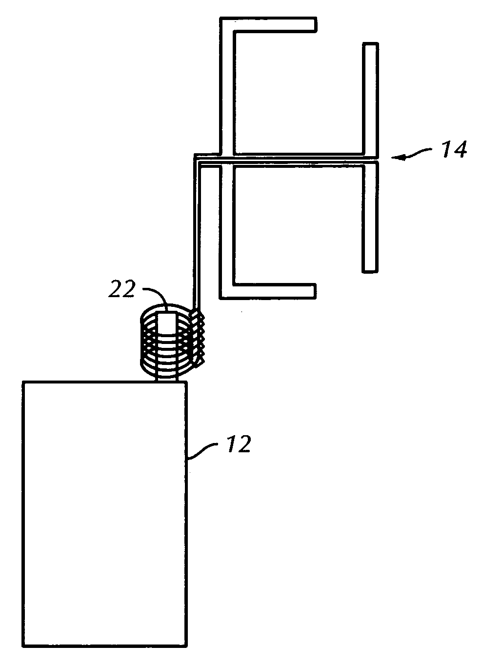
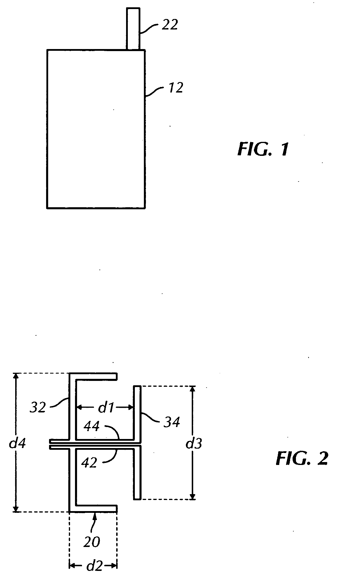
[0031] Referring to the drawings in detail, wherein like numerals indicate like elements throughout, FIG. 1 shows a typical cell phone 12 with a typical external cell phone antenna 22.

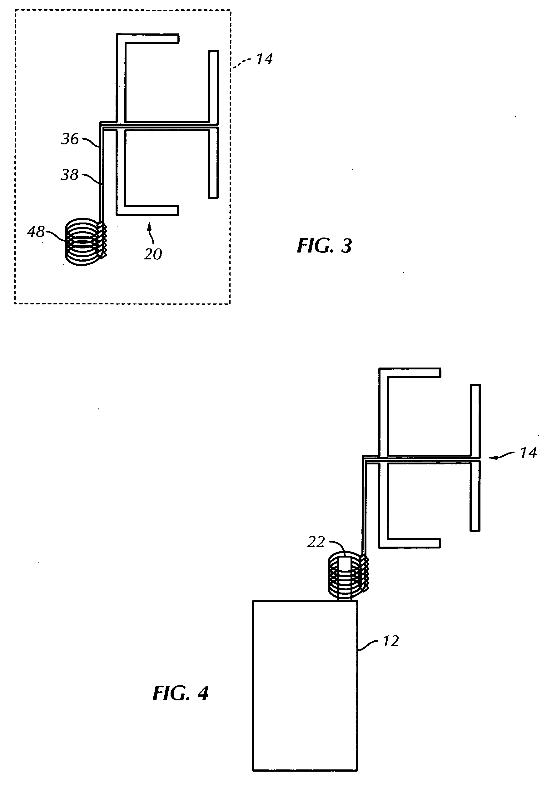
[0032]FIG. 2 shows two different antennas 32 and 34, arranged in an assembly 20 to provide greater cell phone performance enhancement than is available with a single frequency antenna. Antenna 32 is preferably tuned to the 850 MHz band and antenna 34 is preferably tuned to the 1950 MHz band. Dimensions d2, d4 and d2 when combined form a half wavelength [λ / 2] in the 850 MHz band and dimension d3 is a half wavelength [λ / 2] in the 1950 MHz band. Since antenna 32 and antenna 34 operate at different cell phone frequencies, there is no phase relationship between them, except that dimension d1 should preferably be as small as possible to realize the smallest possible overall size of the antenna configuration that incorporates the present invention. By setting dimension d1 at approximately λ / 4 at 1950 MHz, an...


PUM


Abstract

A portable, self contained, dual frequency external antenna configuration is provided for use with a phone, such as a cell phone having either an outwardly extending antenna or an internal antenna to enhance cell phone operation. The antenna configuration comprises a first antenna tuned to a first cell phone operating frequency and a second antenna tuned to a second cell phone operating frequency. A connector is provided, the connector adapted for making a connection to the cell phone and at least one transmission line connects the first and second antennas to the connector.

Description

CROSS-REFERENCE TO RELATED APPLICATIONS [0001] This application is a continuation-in-part of U.S. patent application Ser. No. 11 / 233,908 filed Sep. 23, 2005 and entitled “Personal Portable External Cell Phone Antenna”, now abandoned. This application claims the benefit of U.S. Provisional Patent Applications Nos. 60 / 643,377 filed Jan. 13, 2005; 60 / 650,581 filed Feb. 7, 2005; and 60 / 654,880 filed Feb. 22, 2005, the subject matter of each of which is hereby incorporated herein by reference.BACKGROUND OF THE INVENTION [0002] This invention relates to a portable, self contained device which incorporates patterns of electrically conductive lines in the configuration of one or more antennas tuned to one or more of the operating frequencies of a cell phone which, when connected to the cell phone, enhances the performance of the cell phone. [0003] The need for reliable wireless communication essentially gave rise to two different ways of achieving this result. One such system utilized a set...

Claims


Application Information

Patent Timeline
Patent Type & Authority Applications(United States)
IPC IPC(8): H04M1/00
CPCH01Q1/242H01Q1/38H01Q5/371H01Q21/30H01Q9/285
Inventor BOGNER, BRUCE FREDRIC
Owner BRUCEMARV
Why Eureka
Try Eureka