Lens operation device and camera system
a technology of operation device and camera system, applied in the direction of coupling device connection, camera, instruments, etc., can solve the problem of impossible demand us
- Summary
- Abstract
- Description
- Claims
- Application Information
AI Technical Summary
Benefits of technology
Problems solved by technology
Method used
Image


Examples
first embodiment
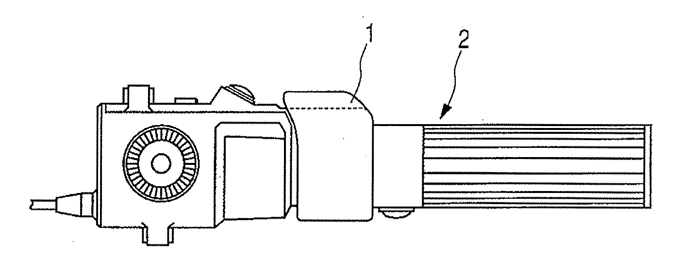
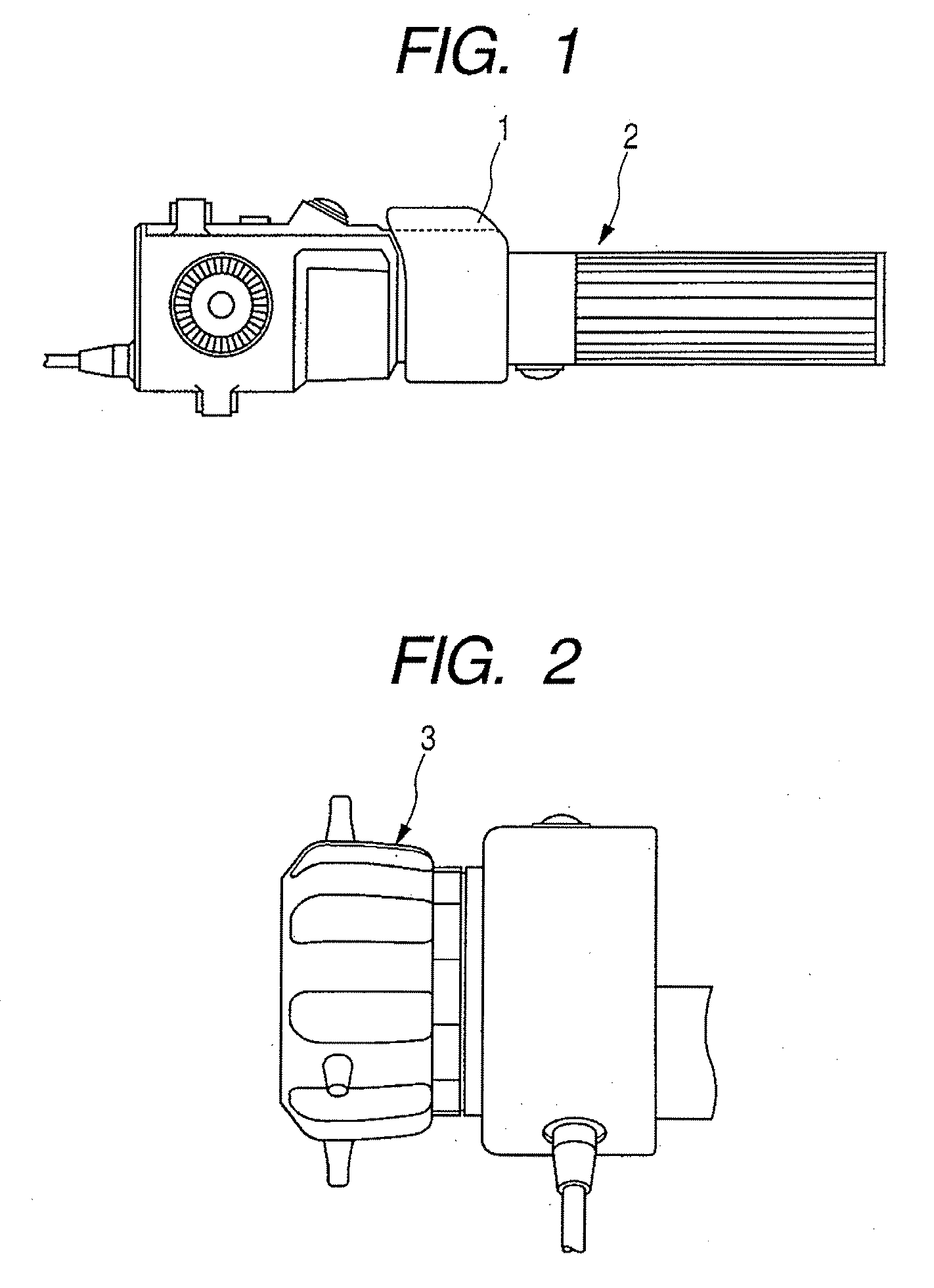
[0023]FIG. 1 shows a zoom demand 2 equipped with a zoom control switch 1 and to be connected to a camera system composed of a television camera and a lens apparatus, and FIG. 2 shows a focus demand 3 which is also to be connected to a camera system.
[0024]FIG. 3 shows a block circuit diagram of the zoom demand 2. A command signal generating circuit 4 outputs a command signal which indicates a driving direction and a driving speed, both of which is in proportion to the operation amount of the zoom control switch 1, which is operated by an operator, in order to electrically drive a zoom lens optical system. The output of the command signal generating circuit 4 is connected to a CPU 8 for performing various control operations, recognition of an lens apparatus, assignment of a function to an auxiliary switch, i.e., AUX switch, and a setting operation via a zoom speed variable resistor 5, a command signal computing unit 6 for effecting signal level conversion and shift conversion, and an...
second embodiment
[0038] While, in first Embodiment described above, one zoom demand 2 is connected to one lens apparatus, it is also possible to connect a plurality of demands to one lens apparatus as shown in FIG. 8. In second Embodiment shown in FIG. 8, a plurality of AUX switches are provided on the zoom demand 2; the reference numerals used are the same as those of first Embodiment. AUX switches 11 and 25 are arranged on the zoom demand 2, and effect enabling / disabling of the functions with which the lens apparatus 26 is endowed, such as quick zoom, shuttle shot, and preset.
[0039]FIG. 9 is an operational flowchart for second Embodiment. When the zoom demand 2 is connected to the lens apparatus 26, a connection recognition signal is transmitted in Step S201 from the zoom demand 2 side to the lens apparatus 26 side through the communication conversion circuit 13. When the lens apparatus 26 and the zoom demand 2 are connected to each other, and the power source of the zoom demand 2 is turned on, i...
third embodiment
[0047] While, in first and second Embodiments described above, the assignment and setting of the function to the AUX switch is effected automatically, in third Embodiment, it is possible to effect switching between automatic setting and setting by a user.
[0048]FIG. 10 shows a display-type user mode setting portion 31 arranged on the zoom demand 2 and connected to the AUX user setting circuit 12 of FIG. 3, making it possible to effect switching between the user setting mode and the automatic setting mode, and the function assignment to the AUX switch. Provided in the user mode setting portion 31 are a setting item, referred to as AUTO, allowing selection between automatic AUX switch function assignment and manual AUX switch function assignment, and setting items, referred to as AUX 1 through 3, allowing setting as to which function is to be assigned to which AUX switch.
[0049] A changeover switch 32 is added to the user mode setting portion 31; the changeover switch 32 effects switc...
PUM
 Abstract
Description
Claims
Application Information
 - R&D
- Intellectual Property
- Life Sciences
- Materials
- Tech Scout
- Unparalleled Data Quality
- Higher Quality Content
- 60% Fewer Hallucinations
Browse by: Latest US Patents, China's latest patents, Technical Efficacy Thesaurus, Application Domain, Technology Topic, Popular Technical Reports.
© 2025 PatSnap. All rights reserved.Legal|Privacy policy|Modern Slavery Act Transparency Statement|Sitemap|About US| Contact US: help@patsnap.com