Rotary device with sensor and method for forming apparatus for measuring load on rolling bearing unit

a technology of a rotary device and a sensor, which is applied in the direction of mechanical equipment, instruments, transportation and packaging, etc., can solve the problems of limited measurement resolution, difficult to reduce the size of the apparatus, and difficulty in measuring the velocity of rolling elements, so as to achieve sufficient reliability and enhance the bond strength of the revolving speed detecting encoder with respect to the retainer

Inactive Publication Date: 2007-01-18
NSK LTD
View PDF6 Cites 29 Cited by
  • Summary
  • Abstract
  • Description
  • Claims
  • Application Information

AI Technical Summary

Benefits of technology

[0030] The aforementioned arrangement such that the retainer has an annular magnet mounted on the side thereof contributes to the reduction of the size of the apparatus as compared with the arrangement such that the annular magnet is disposed on other areas of the bearing.
[0031] Moreover, since the retainer has a back yoke-forming member and a multipolar annular magnet provided thereon, the density of magnetic flux toward the magnetism sensor is raised, making it possible to provide a relatively greater air gap between the annular magnet and the sensor and hence a greater tolerance in production while performing the back yoke function of the annular member to reduce the leakage of magnetism.
[0032] Further, since the multipolar annular magnet is formed by a plastic magnet, the retainer is not subject to vibration such as whirling caused by unbalance due to the weight of magnet.
[0045] Further, the apparatus for measuring the load on a rolling bearing unit according to the invention is arranged such that the area to be detected can be covered by a protective film to prevent the area to be detected from rubbing directly against other members disposed adjacent to the retainers.
[0047] Further, in accordance with the apparatus for measuring the load on a rolling bearing unit according to the invention, the area to be detected on the rubber magnet or plastic magnet used as a revolving speed detecting encoder can be prevented from rubbing against other members. Thus, the falling of powdered or microfibrous ferromagnetic material from the area to be detected can be prevented, making it possible to secure the desired durability of the rolling bearing unit and the desired detection accuracy in measurement of load.
[0061] Further, in accordance with the apparatus for measuring the load on a rolling bearing unit of the invention, the bond strength of the revolving speed detecting encoder with respect to the retainer can be enhanced, making it possible to prevent the encoder from being separated from the retainer and hence provide the load measuring apparatus with a sufficient reliability even after a prolonged use.

Problems solved by technology

However, among the aforementioned related art rotary devices with sensor, the rotary device with sensor disclosed in JP-A-2001-033469 is disadvantageous in that the mounting of the magnetism sensor on the rotary device requires the provision of a magnetic encoder or sensor and a member for fixing it, making it difficult to reduce the size of the apparatus.
Further, the method involving the measurement of the velocity of rolling elements is disadvantageous in that the resolution of measurement is limited by the number of rolling elements.
However, the aforementioned rotary speed detecting device is disadvantageous in that the direction of the magnetic pole of the magnetized rolling elements is not always toward the hall element, making it impossible for the hall element to change in its magnetic flux and detect the passage of the magnetized rolling elements when the sensitive surface of the hall element and the direction of the magnetic flux are parallel to each other.
As a result, the accuracy of measurement is deteriorated.
In addition, the operator is informed of the fact that the vehicle is abnormally loaded.
Since such a noncontact sensor having a high precision is expensive, it unavoidably adds to the total cost of the rolling bearing unit with load measuring device.
Therefore, combined with the expensiveness of the load sensor 120 itself, the total cost of the load measuring device of the rolling bearing unit increases unavoidably.
Moreover, the method disclosed in JP-B-62-3365 requires that part of the member corresponding to outer ring have a reduced rigidity, possibly making it difficult to provide the member corresponding to outer ring with a desired durability.
Thus, it is likely that the retainers can make displacement by the amount corresponding to the pocket gap, causing the loss of the measurement gap.
Since the powdered or microfibrous material is made of a ferromagnetic material having a high hardness such as ferrite and iron, it can damage the rolling contact area of the rolling surface of the rolling elements with the outer ring race and the inner ring race when exfoliated to contaminate the grease.
As a result, the durability of the rolling bearing unit comprising the load measuring device incorporated therein can be impaired (rolling fatigue life can be reduced).
Further, the contamination of the grease by the powdered or microfibrous material may cause the deterioration of the detecting precision of the revolving speed detecting sensor.

Method used


Image

  • Rotary device with sensor and method for forming apparatus for measuring load on rolling bearing unit
  • Rotary device with sensor and method for forming apparatus for measuring load on rolling bearing unit
  • Rotary device with sensor and method for forming apparatus for measuring load on rolling bearing unit

Examples


Embodiment Construction

of the invention;

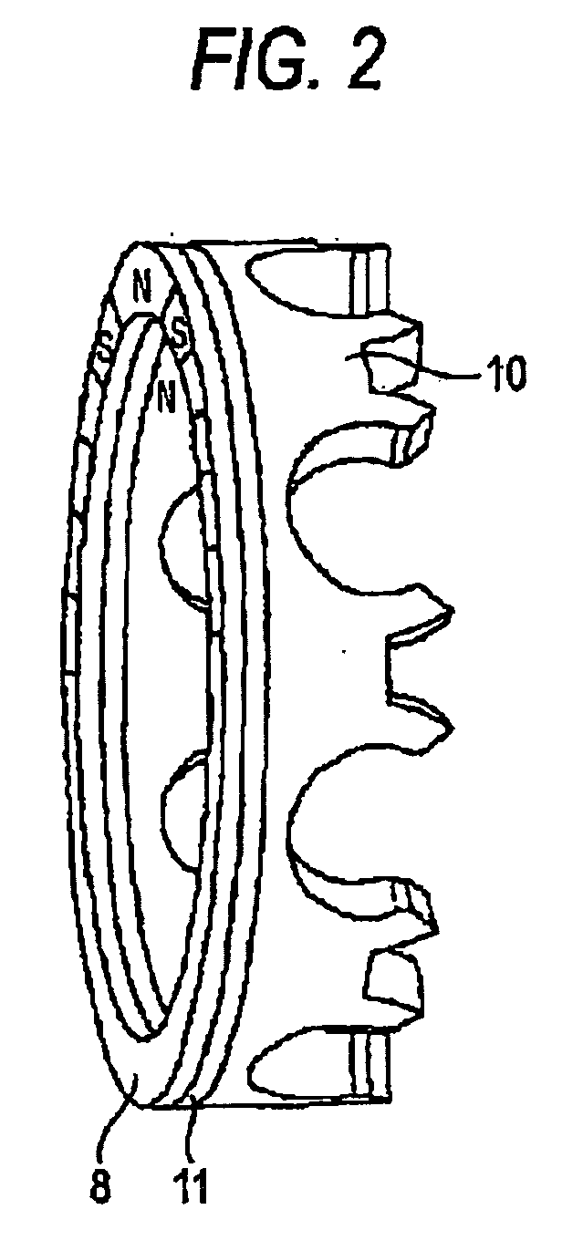
[0063]FIG. 2 is a perspective view of a crown retainer illustrating Example 2;

[0064]FIG. 3 is a diagram illustrating the positional relationship between the crown retainer and the sensor;

[0065]FIG. 4 is a sectional view illustrating Example 3 in which the invention is applied to a hub unit for wheel bearing;

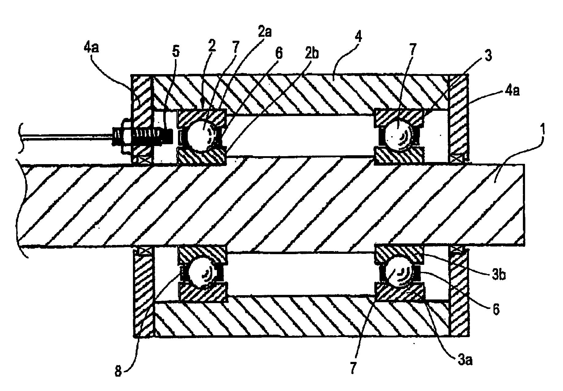
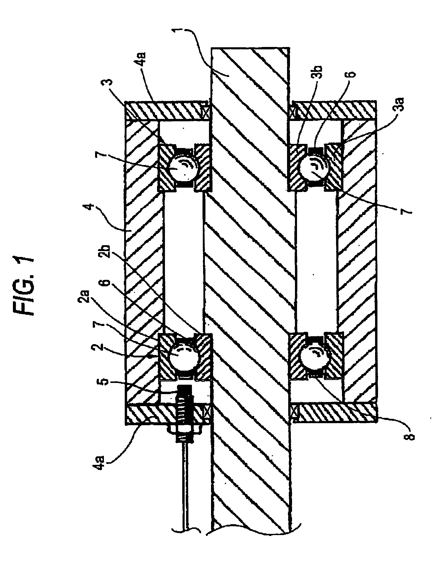
[0066]FIG. 5 is a sectional view illustrating a structure on which the apparatus for measuring the load on a rolling bearing unit of the invention is based;

[0067]FIG. 6 is an enlarged view of the part A of FIG. 5;

[0068]FIG. 7 is a diagram as viewed from above the structure of FIG. 6 with the retainers, rolling elements, revolving speed detecting encoders and revolving speed detecting sensors removed;

[0069]FIG. 8 is a diagram of a rolling bearing unit for illustrating the reason why the load can be measured on the basis of rotary speed;

[0070]FIG. 9 is a partial sectional view of a retainer having a revolving speed detecting encoder connected thereto and a s...


PUM


Abstract

A rotary device includes: a main body; a rolling bearing attached to the main body, the rolling bearing including an inner ring, an outer ring and a retainer rollably retaining rolling elements; an annular magnet having a multipolar magnetization; a back yoke-forming member; and a magnetism sensor disposed on the main body. The annular magnet and the back yoke-forming member are integrally provided on the retainer and disposed opposed to the magnetism sensor separated by a predetermined distance.

Description

TECHNICAL FIELD [0001] The present invention relates to a rotary device with a sensor capable of measuring the rotary speed of the retainer of the bearing used in a rotary device to detect the rotary speed of the rotary shaft or estimate the load on the bearing and a method for forming the rotary device. [0002] Further, the apparatus for measuring the load on a rolling bearing unit according to the invention concerns improvements in rolling bearing unit for bearing the wheel of a moving body such as automobile, railroad vehicle and transporting vehicle and is used to measure the load on the rolling bearing unit (either or both of radial load and axial load) for the purpose of securing the stability in the trip of the moving body. BACKGROUND ART [0003] Heretofore, a rotary device for detecting the rotary speed of the rotary shaft born by a bearing has normally had a magnetic encoder mounted on the rotary portion of the bearing and a magnetism sensor disposed opposed to the former mag...

Claims


Application Information

Patent Timeline
IPC IPC(8): F16C32/00F16C19/18F16C19/52F16C19/54F16C33/41G01P3/44G01P3/487
CPCF16C19/186F16C19/522F16C19/54G01P3/487F16C41/007F16C2326/02G01P3/443F16C33/416F16C19/52G01P3/44F16C19/18F16C33/41
Inventor AOKI, MAMORUONO, KOICHIROYANAGISAWA, TOMOYUKI
Owner NSK LTD
Why Eureka
Try Eureka