Antenna couplers and method of production
a technology of antenna couplers and couplers, applied in the field of antenna couplers, can solve the problems of bulky test equipment, difficult to reach conveniently, and relatively expensive and bulky test equipment, and achieve the effects of reducing the size, complexity and cost of antenna couplers, and low cos
- Summary
- Abstract
- Description
- Claims
- Application Information
AI Technical Summary
Benefits of technology
Problems solved by technology
Method used
Image
Examples
second embodiment
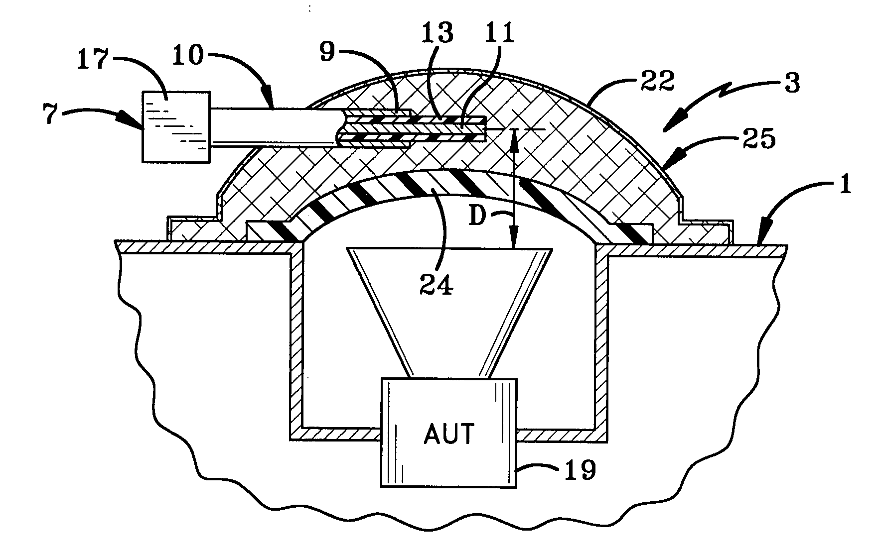
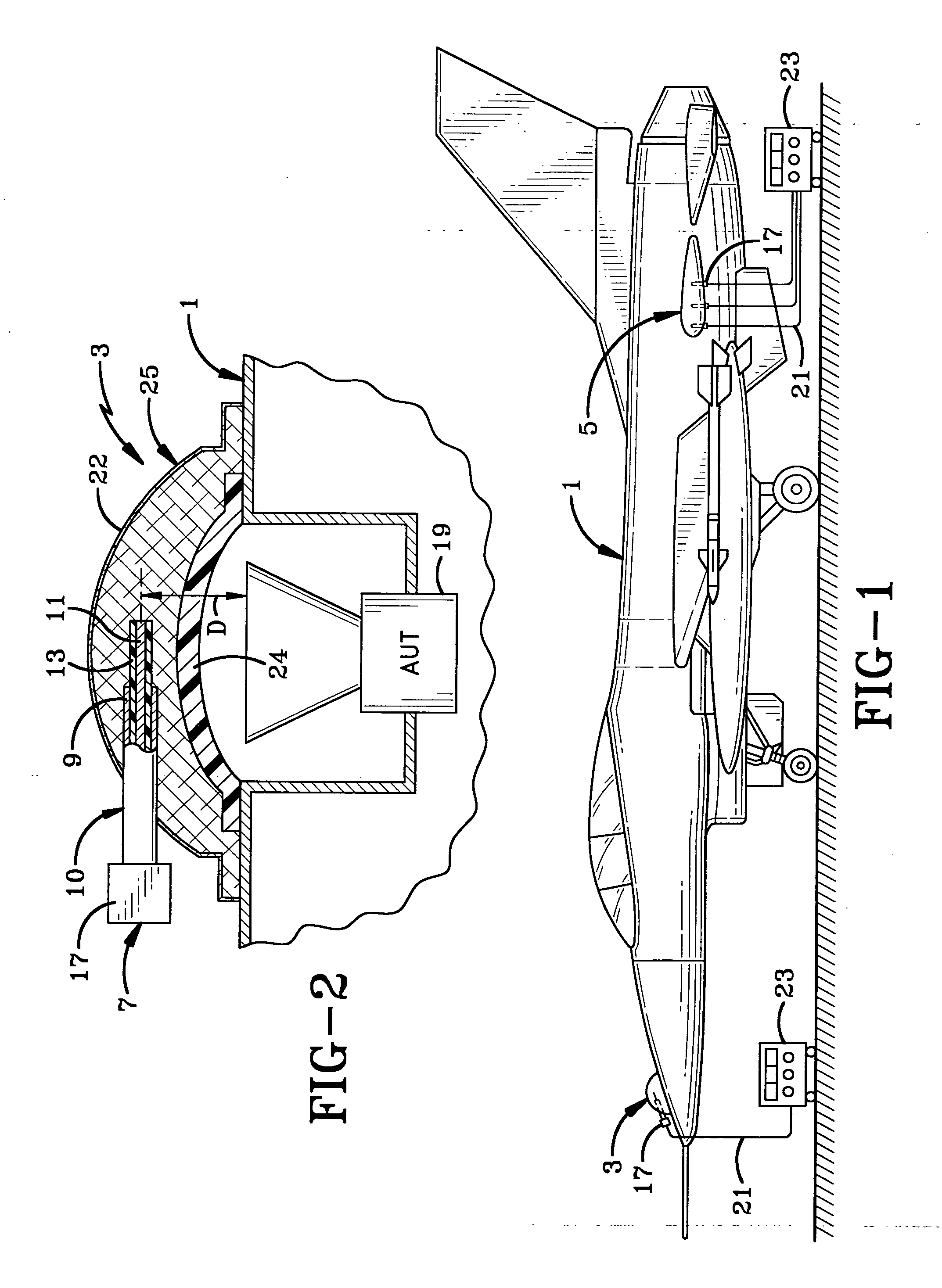
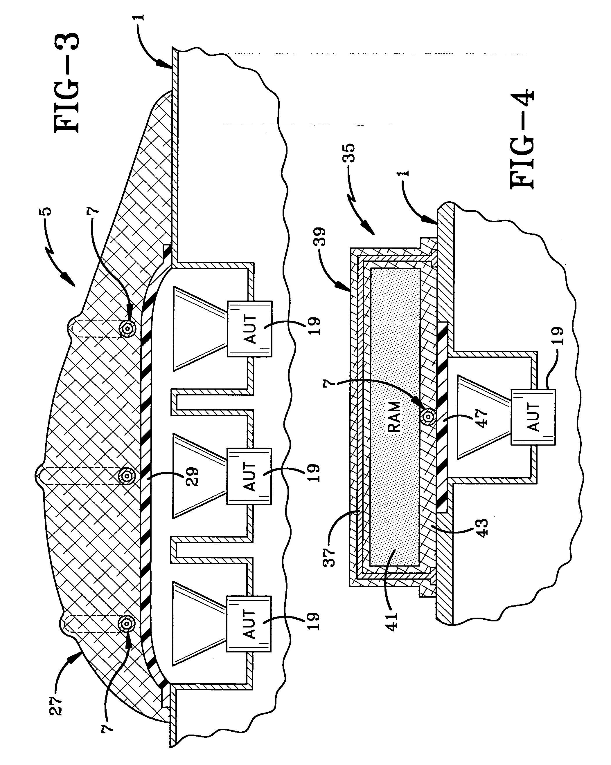
[0024] the antenna coupler indicated at 5, is shown in detail in FIG. 3, and is similar in most respects to coupler 3 discussed above except that it includes a plurality or an array of individual probes 7 spaced from each other throughout a coupler shell 27. Shell 27 also is fabricated from laid-up sheets of fiberglass shaped so that it conforms to the shape of the aircraft, and in particular to the radome 29 thereof, so that probes 7 formed from coaxial cables 10, are located at the required distances from the apertures of the multiple AUT 19. Each of the coaxial cables 10 embedded in shell 27 have an RF connector 17 at the exposed ends thereof for connection to test equipment 23 as shown in FIG. 1.
third embodiment
[0025] A third embodiment is indicated generally at 35 (FIG. 4), and is similar to embodiments 3 and 5 discussed above with the exception that it includes a metallic screen 37 embedded within a dielectric shell 39 where it is separated from probe 7 by a layer of radar absorbent material (RAM) indicated at 41. Probe 7 will be embedded within an innermost layer 43 of the fiberglass so as to be at the correct spacing from the aperture of an AUT 19. Again, as shown in FIG. 4, dielectric shell 39 is placed over an aircraft radome 47 eliminating the need for removal of the same as required in prior tests. Also, a gel-coat layer (not shown) may be placed over the layers of fiberglass in forming the finalized dielectric shell 39.
[0026] As discussed above, probe 7 shown in the various embodiments will-have an exposed center conductor equal to or less than ¼ wavelength at the low end of the operating frequency range of the aperture of the AUT. As examples, a 500 MHz antenna signal will have a...
PUM
 Abstract
Description
Claims
Application Information
 - R&D
- Intellectual Property
- Life Sciences
- Materials
- Tech Scout
- Unparalleled Data Quality
- Higher Quality Content
- 60% Fewer Hallucinations
Browse by: Latest US Patents, China's latest patents, Technical Efficacy Thesaurus, Application Domain, Technology Topic, Popular Technical Reports.
© 2025 PatSnap. All rights reserved.Legal|Privacy policy|Modern Slavery Act Transparency Statement|Sitemap|About US| Contact US: help@patsnap.com


