0th droop detector architecture and implementation
a detector and 0th droop technology, applied in the field of voltage detection circuitry, can solve the problems of inability to accurately measure the 0sup>th /sup>droop from outside the chip, amplifier must have a very high bandwidth, and the available technology cannot accurately measure the 0sup>th /sup>droop
- Summary
- Abstract
- Description
- Claims
- Application Information
AI Technical Summary
Problems solved by technology
Method used
Image
Examples
Embodiment Construction
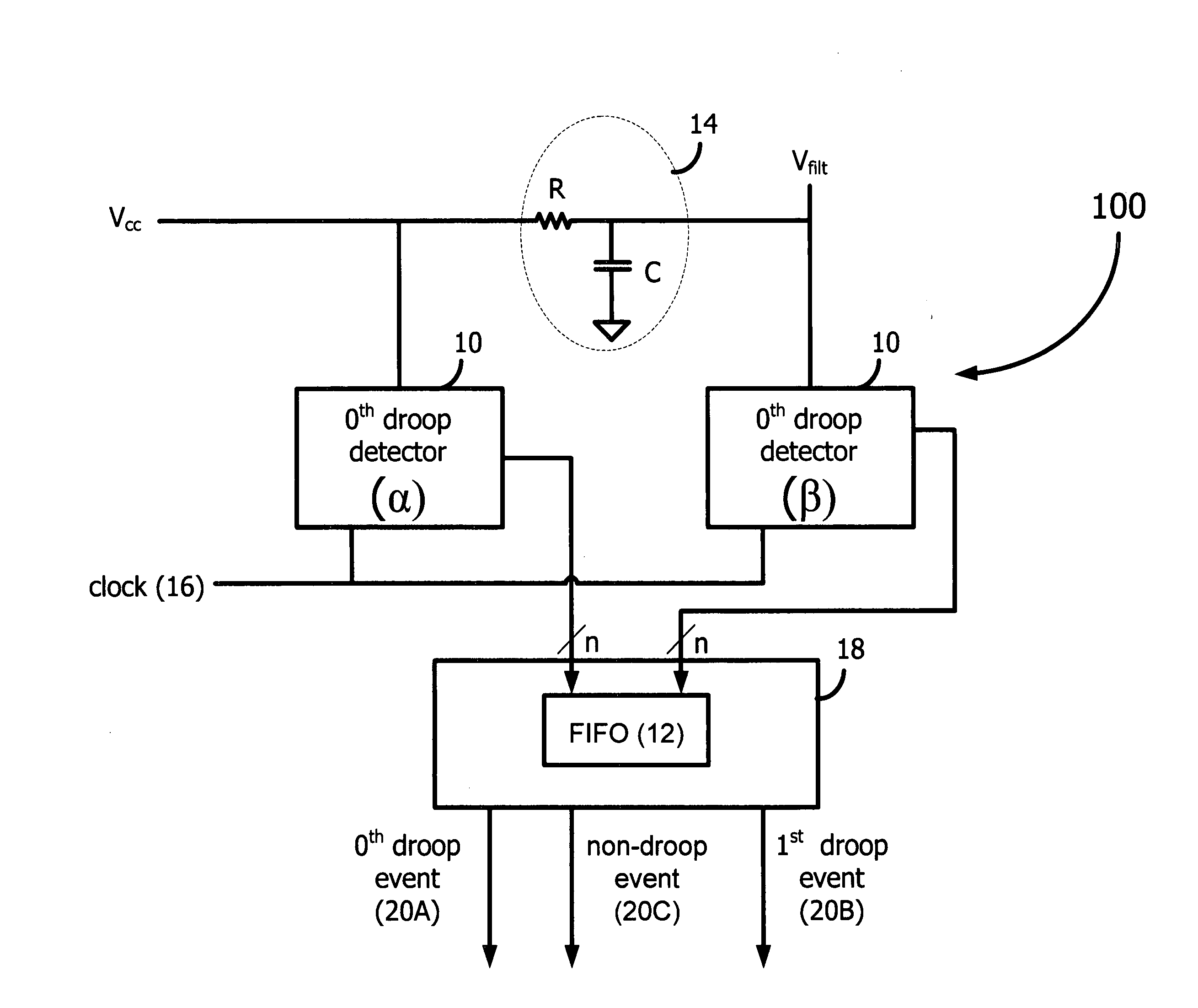
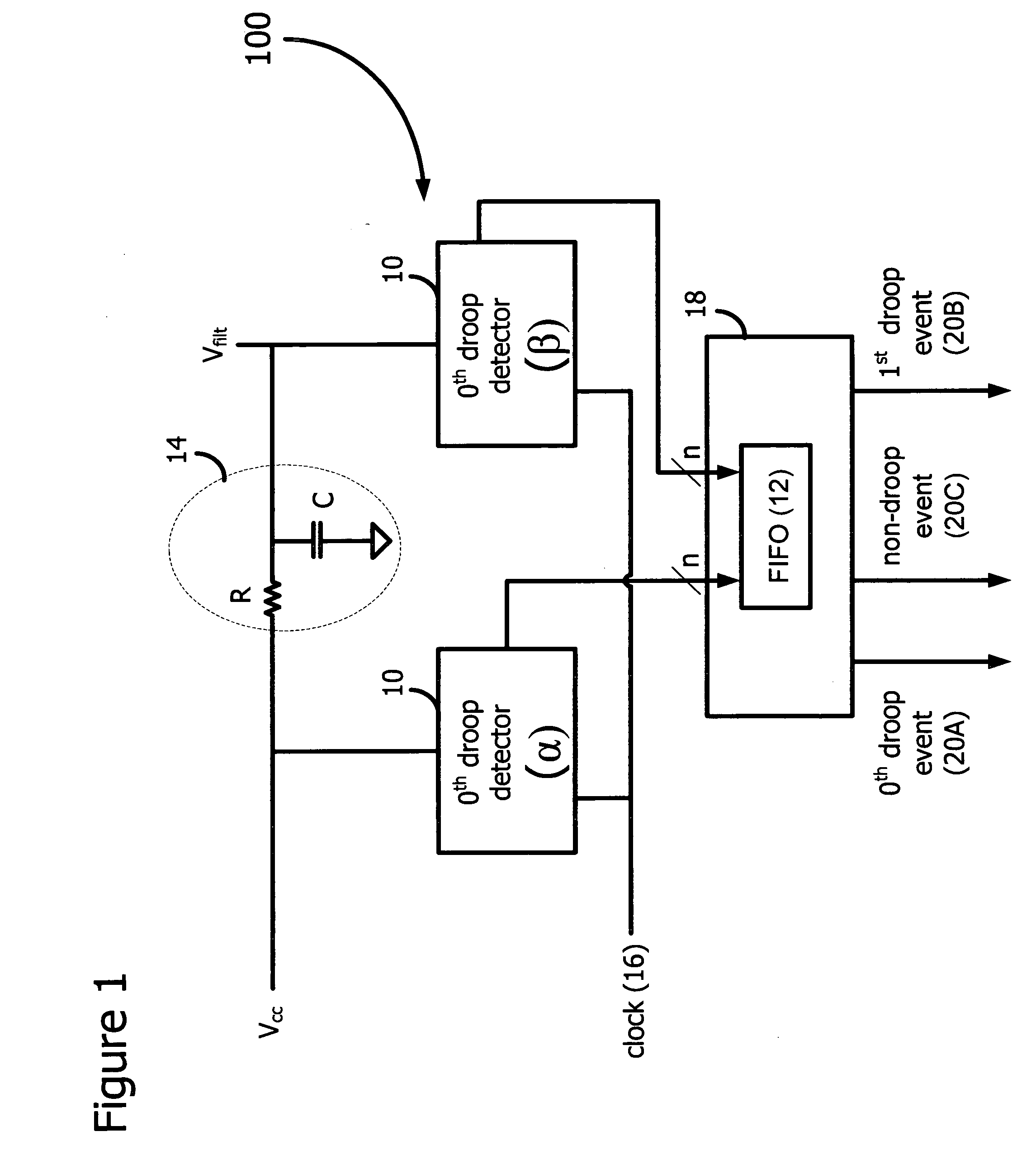
[0017] In accordance with the embodiments described herein, a voltage droop detector is disclosed for capturing the very high-frequency noise on the power grid of a load, such as a microprocessor. The droop detector includes twin circuits, one of which receives the voltage from the power grid of the load, the other of which receives a filtered voltage. A droop detected by the first circuit but not the second circuit, deemed the 0th droop, as well as 1st droop, 2nd droop, and so on, are captured and stored for subsequent analysis. The circuits sample the voltages frequently enough to ensure capture of the 0th droop event.
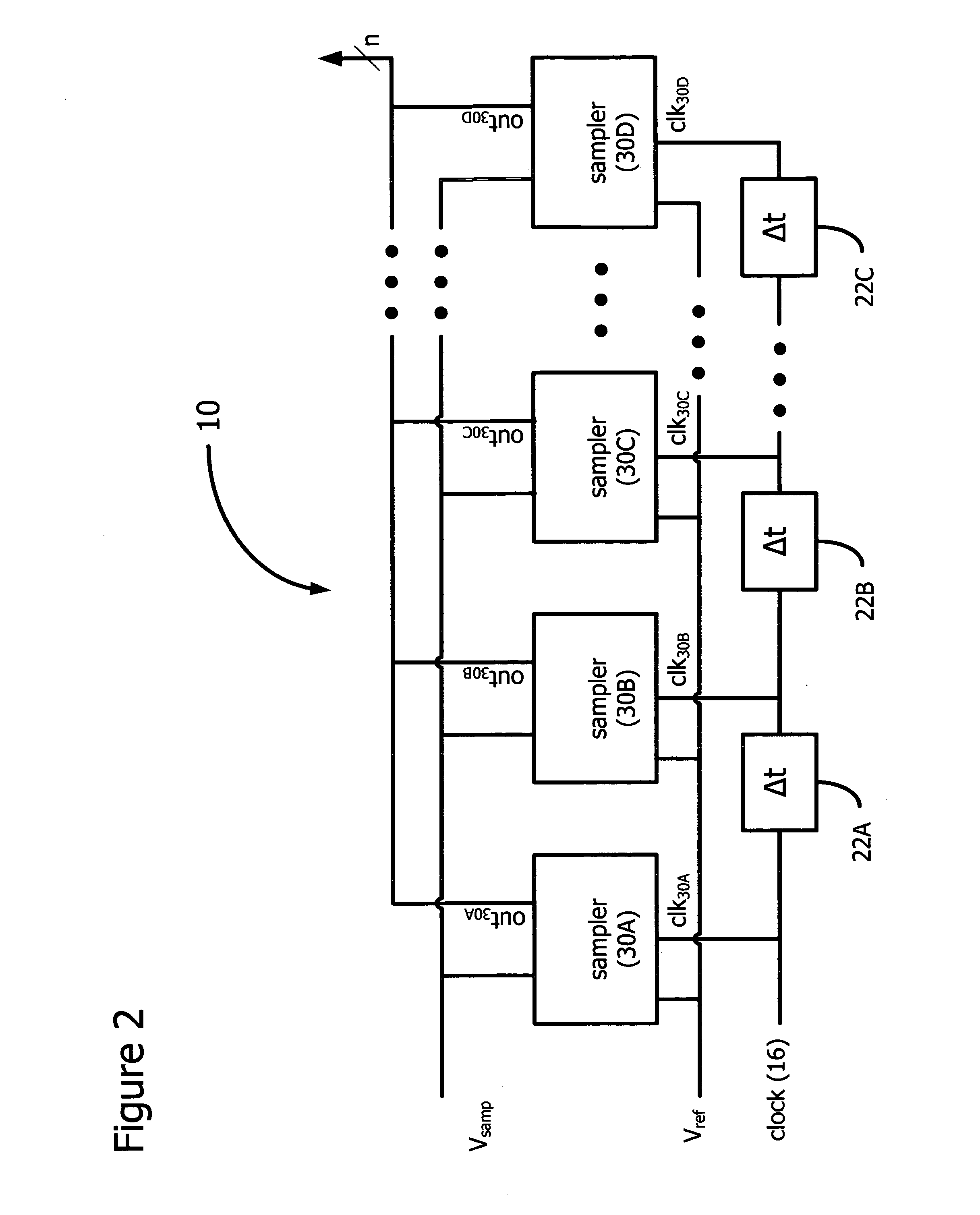
[0018] The voltage droop detector architecture described herein, in contrast to the prior art, exploits a semi-synchronous continuous digital sampling technique to identify and record 0th droop events. Prior art droop detectors are generally analog solutions whose speed limitations render them incapable of capturing the 0th droop event.
[0019] In the following detai...
PUM
 Abstract
Description
Claims
Application Information
 - R&D
- Intellectual Property
- Life Sciences
- Materials
- Tech Scout
- Unparalleled Data Quality
- Higher Quality Content
- 60% Fewer Hallucinations
Browse by: Latest US Patents, China's latest patents, Technical Efficacy Thesaurus, Application Domain, Technology Topic, Popular Technical Reports.
© 2025 PatSnap. All rights reserved.Legal|Privacy policy|Modern Slavery Act Transparency Statement|Sitemap|About US| Contact US: help@patsnap.com


