
Biometric sensor and biometric method

a biometric sensor and sensor technology, applied in the field of living body measuring sensor and living body measuring method, can solve the problems of inability to retrieve the living body electric signal, method is rather awkward, surface soreness, etc., and achieve the effect of less invasiveness

Inactive Publication Date: 2007-01-11
GRACO CHILDRENS PROD INC
View PDF8 Cites 68 Cited by
  • Summary
  • Abstract
  • Description
  • Claims
  • Application Information

AI Technical Summary

Benefits of technology

[0009] Therefore, an object of the present invention is to provide a living body measuring sensor and a living body measuring method capable of measuring an electrocardiogram using a capacitance in a less invasive manner.
[0011] According to the present invention, the conductive electrode is mounted on the body surface of the measuring subject via the insulating member and the living body electric signal is outputted as the low impedance signal. Thereby, the electrocardiogram can be measured in the less invasive manner without any adverse effect from the noise, and a risk of inducing an allergic reaction can be eliminated.

Problems solved by technology

When the fixed electrode 51 is attached to the body surface for as long as a few hours, the surface in contact with the electrode becomes itchy or an allergic reaction may cause the surface to be sore due to inflammation.
However, the method is rather awkward because an output of the fixed voltage 51 shows a high impedance and a noise voltage is thereby increased as shown in FIGS. 10B and 10C in response to an even slight amount of noise current, which results in a failure to retrieve the living body electric signal. FIG. 10B shows an output voltage of the fixed electrode 51 when silk is interposed, while FIG. 10C shows an output voltage thereof when cotton is interposed.
However, in the case of using the conductive fiber as the induction electrode, the conductive fiber may fail to closely contact the skin, which cannot assure an accurate electrocardiogram.
Further, the conductive fiber includes the risk of inducing the allergic reaction in the same manner as in the metal electrode.

Method used


Image

  • Biometric sensor and biometric method
  • Biometric sensor and biometric method
  • Biometric sensor and biometric method

Examples


Embodiment Construction

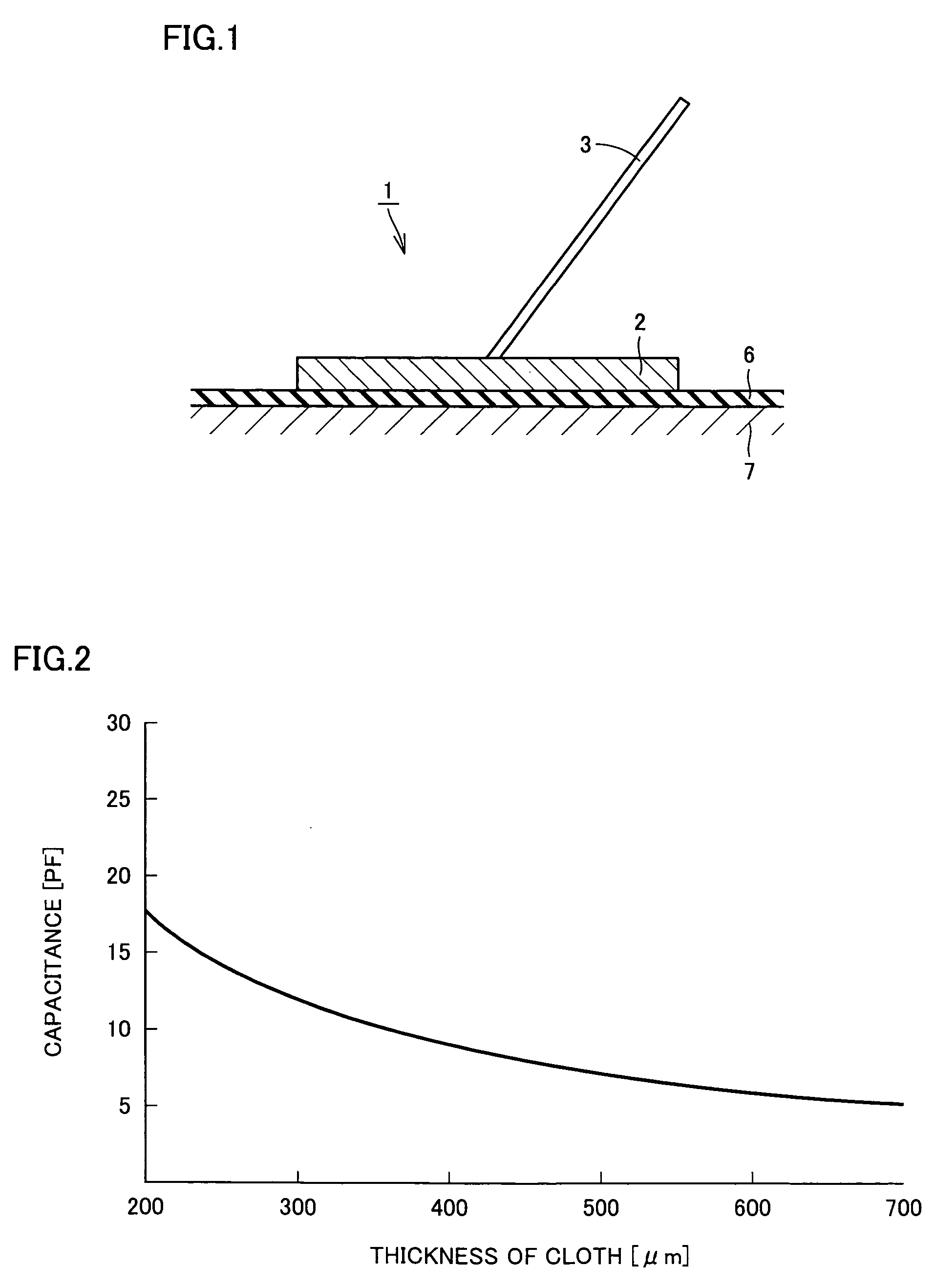
[0035]FIG. 1 is a sectional view of a living body measuring sensor according to an embodiment of the present invention. A living body measuring sensor 1 shown in FIG. 1 employs a contact made by means of capacitance coupling without any direct contact with a skin 7 of a measuring subject as a measurement principle. A silver electrode 2, which is an example of a metal electrode as a conductive electrode, is provided. The silver electrode 2 is formed in a thin disk shape or rectangular shape. The conductive electrode is not limited to the silver electrode 2, and may employ stainless, aluminum, a conductive cloth, a conductive gel or the like.

[0036] The living body measuring sensor 1 is brought into close contact with a surface of the skin 7 via a thin cloth 6 formed from silk or the like serving as an insulating member so as to detect a variation of a living body electric signal generated on the body surface of the measuring subject.

[0037]FIG. 2 is a graph showing a relationship bet...


PUM


Abstract

A living body measuring sensor (1) is made to contact a body surface of a measuring subject through capacitance coupling using a cloth (6) between a metal electrode (2) and the body surface as the capacitance, a living body electric signal is extracted from the metal electrode (2), and an elctrocardiographic waveform is outputted based on an output of the living body measuring sensor (1) using an impedance converter having a high input impedance and a low output impedance.

Description

TECHNICAL FIELD [0001] The present invention relates to a living body measuring sensor and a living body measuring method, more particularly to a living body measuring sensor and a living body measuring method for obtaining an electrocardiogram without making a direct contact with a body surface of a measuring subject. BACKGROUND ART [0002] An electrocardiogram obtained by a conventional electrocardiograph records a ventricular function measured at rest, wherein a variation of a voltage generated on a body surface of a measuring subject is recorded. The electrocardiogram is a record of an electric activity generated in a heart pulsation, wherein the voltage generated on the body surface as a result of a cardiac muscle excited by generation and propagation of stimulations prior to a cardiac contraction is recorded using a curved line. [0003]FIG. 9 is a schematic block diagram of a conventional electrocardiograph. For the purpose of the measurement of the electrocardiogram, a fixed el...

Claims


Application Information

Patent Timeline
IPC IPC(8): A61B5/04A61B5/0478A61B5/0408A61N1/04
CPCA61B5/0408A61N1/0484A61B5/411A61B2562/0215A61B5/25A61B5/27A61B5/265A61B5/256A61B5/28A61B5/277
Inventor UENO, AKINORIISHIYAMA, YOJIHOSHINO, HIROSHIKASSAI, KENZOUSUZUKI, SACHIYO
Owner GRACO CHILDRENS PROD INC
Learn More