
Cabin pressure control system and method that implements high-speed sampling and averaging techniques to compute cabin pressure rate of change

a control system and cabin pressure technology, applied in fluid pressure control, instrumentation, energy-saving board measures, etc., can solve problems such as system failure, system failure, and aircraft passengers' hypoxia, so as to reduce or eliminate motor dithering, reduce cost, and reduce circuit noise.

Inactive Publication Date: 2007-01-11
HONEYWELL INT INC
View PDF18 Cites 5 Cited by
  • Summary
  • Abstract
  • Description
  • Claims
  • Application Information

AI Technical Summary

Benefits of technology

[0009] The present invention provides a cabin pressure control system and method that is less susceptible to circuit noise, and / or reduces or eliminates motor dither and thus motor and gear wear, and / or that can be implemented with lower cost pressure sensors and circuits.

Problems solved by technology

Thus, unless otherwise controlled, air could leak out of the aircraft cabin causing it to decompress to an undesirably low pressure at high altitudes.
If the pressure in the aircraft cabin is too low, the aircraft passengers may suffer hypoxia, which is a deficiency of oxygen concentration in human tissue.
Although most cabin pressure control systems that implement cabin pressure rate of change control laws operate safely, reliably, and robustly, these systems can suffer certain drawbacks.
In particular, the sensed cabin pressure rate of change value can be noisy about the actual cabin pressure rate of change.
For example, if sensed cabin pressure is differentiated using an analog circuit, the circuit typically includes a relatively high-gain rate amplifier that is susceptible to electrical noise.
The sensed rate noise noted above can cause the control laws to undesirably supply commands to the outflow valve motor that cause motor dither.
Motor dither can cause wear on both the outflow valve motor and other components, such as gearing, that may couple to the motor to the outflow valve.
Moreover, if the analog-to-digital conversion circuit is implemented as part of the cabin pressure sensor (e.g., a so-called “digital sensor”), this can result in increased sensor cost, increased transducer circuit cost, and / or relatively large sensor and circuit footprint.

Method used


Image

  • Cabin pressure control system and method that implements high-speed sampling and averaging techniques to compute cabin pressure rate of change
  • Cabin pressure control system and method that implements high-speed sampling and averaging techniques to compute cabin pressure rate of change
  • Cabin pressure control system and method that implements high-speed sampling and averaging techniques to compute cabin pressure rate of change

Examples


Embodiment Construction

[0016] Before proceeding with the description, it is to be appreciated that the following detailed description is merely exemplary in nature and is not intended to limit the invention or the application and uses of the invention. Furthermore, there is no intention to be bound by any theory presented in the preceding background or the following detailed description.

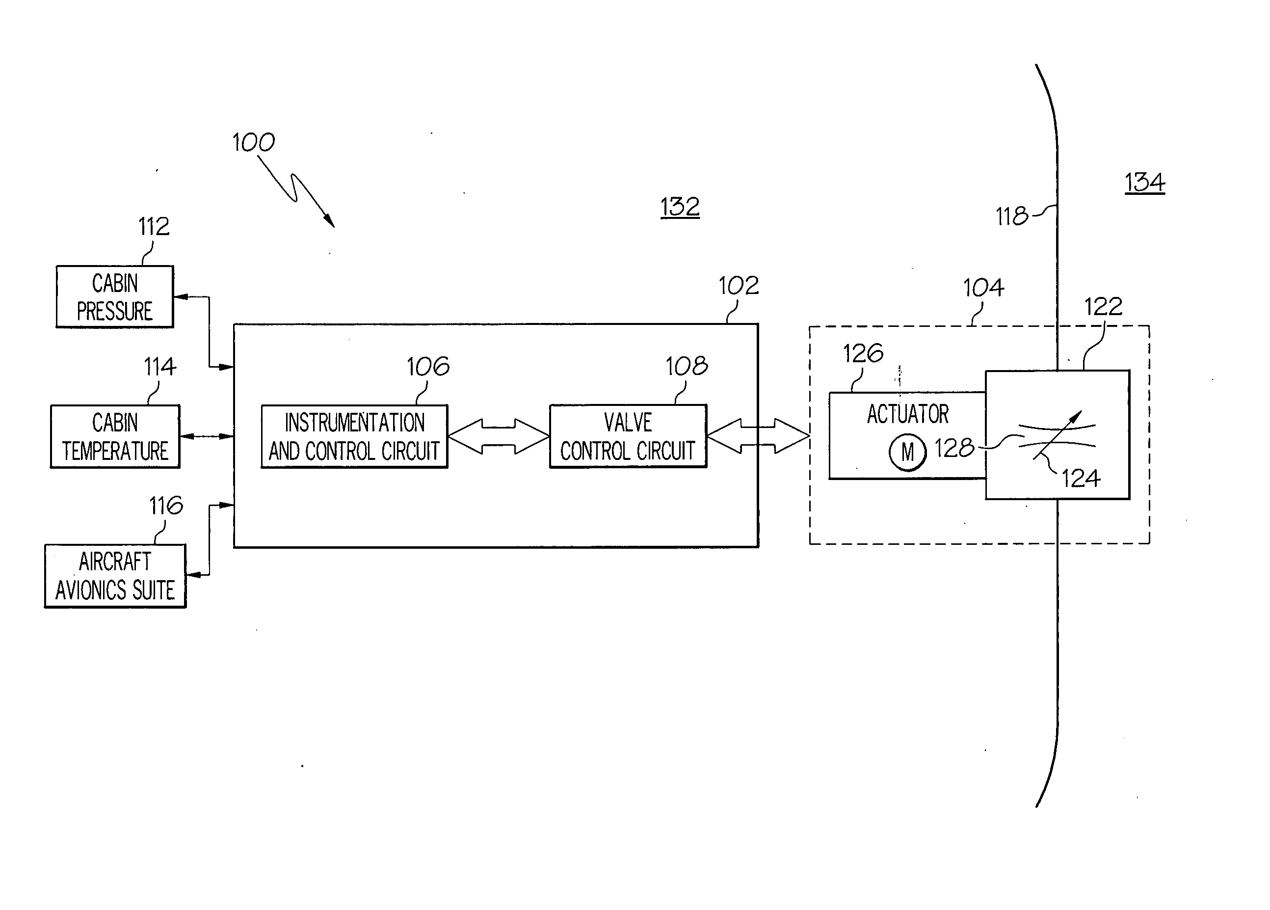
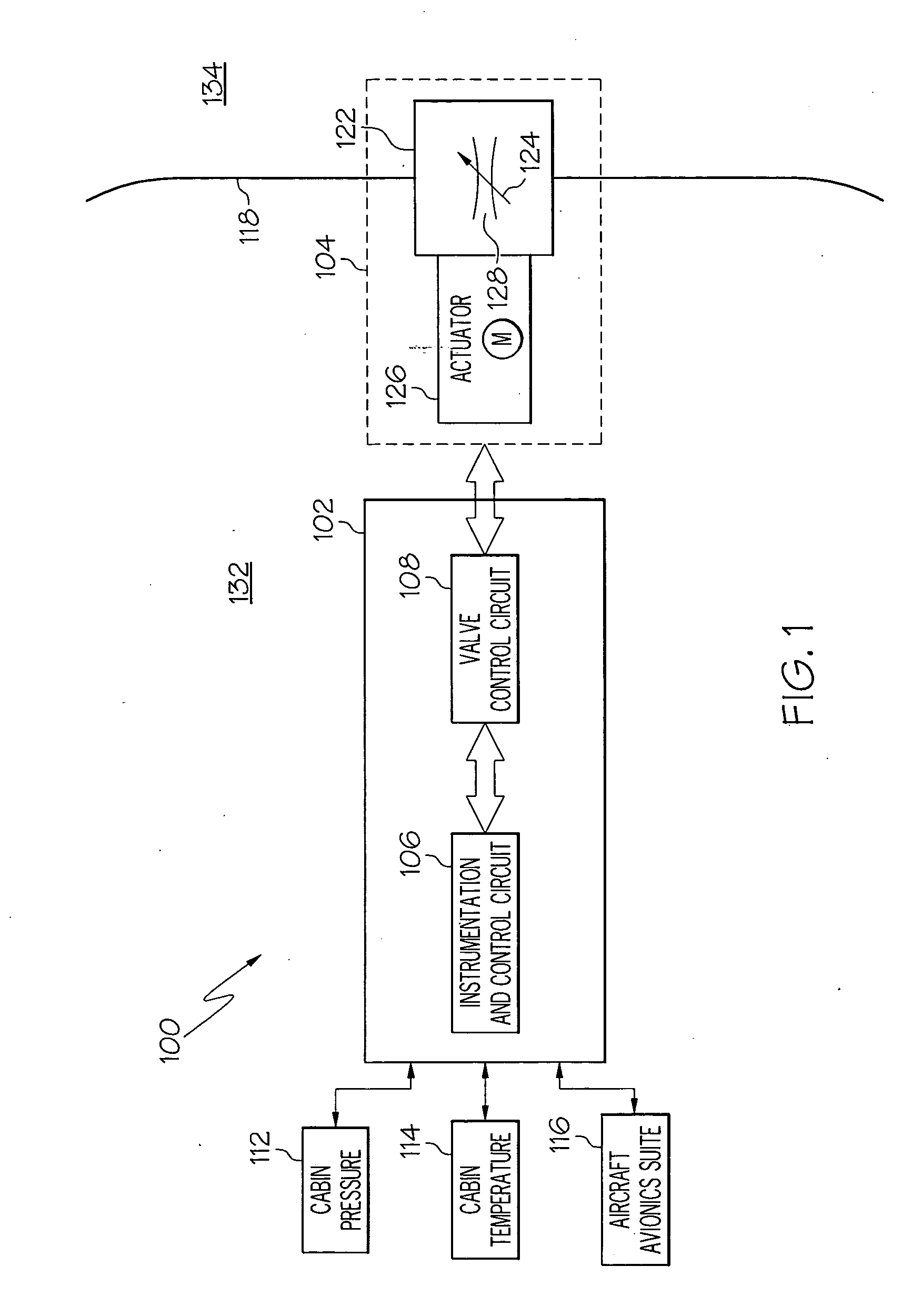
[0017] Turning now to FIG. 1, a functional block diagram of an exemplary aircraft cabin pressure control system 100, and its interconnections to certain other aircraft systems, is shown. In the depicted embodiment, the system 100 includes a control unit 102 and an outflow valve 104. Although not depicted, it will be appreciated that the system 100 may additionally include one or more overpressure relief valves, and one or more negative pressure relief valves. These valves are typically included as part of an aircraft cabin pressure control system but, for clarity and ease of illustration and depiction, are not shown or fu...


PUM


Abstract

An aircraft cabin pressure control system and the method implement a technique that oversamples and filters a sensed cabin pressure signal, and then differentiates the oversampled and filtered pressure signal to generate cabin pressure rate-of-change. The oversampling and filtering technique removes circuit and sensor induced noise from the cabin pressure signal, and results in cabin pressure rate-of-change values with less noise than currently known systems and methods.

Description

TECHNICAL FIELD [0001] The present invention relates to aircraft cabin pressure control and, more particularly, to an aircraft cabin pressure control system and method for computing cabin pressure rate of change. BACKGROUND [0002] For a given airspeed, an aircraft may consume less fuel at a higher altitude than it does at a lower altitude. In other words, an aircraft may be more efficient in flight at higher altitudes as compared to lower altitudes. Moreover, bad weather and turbulence can sometimes be avoided by flying above such weather or turbulence. Thus, because of these and other potential advantages, many aircraft are designed to fly at relatively high altitudes. [0003] As the altitude of an aircraft increases, from its take-off altitude to its “top of climb” or “cruise” altitude, the ambient atmospheric pressure outside of the aircraft decreases. Thus, unless otherwise controlled, air could leak out of the aircraft cabin causing it to decompress to an undesirably low pressur...

Claims


Application Information

Patent Timeline
IPC IPC(8): B64D13/02
CPCB64D13/04G01L9/065Y02T50/56G05D16/2013Y02T50/50
Inventor HORNER, DARRELL W.MCCOY, GERARD L.BISS, TIMOTHY C.
Owner HONEYWELL INT INC
Learn More