
System and method for accelerated clock synchronization of remotely distributed electronic devices

a technology of electronic devices and clocks, applied in the direction of television systems, instruments, generating/distributing signals, etc., can solve the problems of inability to detect the master device may not be able to properly interpret the data being transmitted, and the master device may not be able to recognize the throughput degradation attributable to a slow acquisition rate, so as to accelerate the acquisition rate and secure the signal lock more quickly, the effect of reducing

Inactive Publication Date: 2007-01-11
AVAGO TECH INT SALES PTE LTD
View PDF9 Cites 8 Cited by
  • Summary
  • Abstract
  • Description
  • Claims
  • Application Information

AI Technical Summary

Benefits of technology

This approach significantly improves the acquisition rate, reducing the time to lock onto a clock signal by approximately 84% in cable modem systems, enhancing operational efficiency and data throughput.

Problems solved by technology

If the devices are not properly synchronized, the receiving device may not be able to properly interpret data being transmitted to it.
If the clocks of the remote devices are not synchronized with the clock of the master device, an undesirable situation may arise, such that, the remote devices transmit data at the same time or in the wrong time slots leading to confusion and loss of data at the master device.
When a PLL system is acquiring lock upon system start-up, the throughput degradation attributable to a slow acquisition rate may not be perceptible.
However, when a system is operating and lock is lost, having a slow acquisition rate may significantly degrade performance.
While start-up acquisition, by definition, only occurs once, re-acquisition during operation may occur many times. Because the re-acquisition occurs while data is likely being transmitted, data may be lost.
The longer the re-acquisition, the more data is lost and the greater the time needed to recover the data.
Depending on how often clock synchronization is lost, this could result in a performance degradation of up to 10%.
While there currently are approaches to aid a PLL system to achieve lock and to reduce acquisition rates, these approaches are either relatively slow given current communication speeds or require complex circuitry.

Method used


Image

  • System and method for accelerated clock synchronization of remotely distributed electronic devices
  • System and method for accelerated clock synchronization of remotely distributed electronic devices
  • System and method for accelerated clock synchronization of remotely distributed electronic devices

Examples


Embodiment Construction

[0025] While the present invention is described herein with reference to illustrative embodiments for particular applications, it should be understood that the invention is not limited thereto. Those skilled in the art with access to the teachings provided herein will recognize additional modifications, applications, and embodiments within the scope thereof and additional fields in which the invention would be of significant utility.

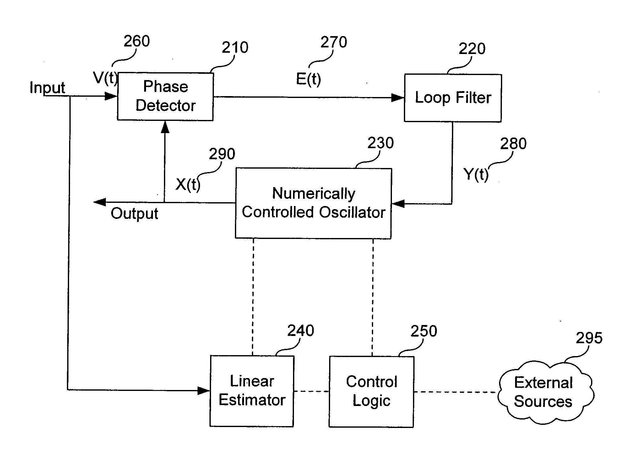
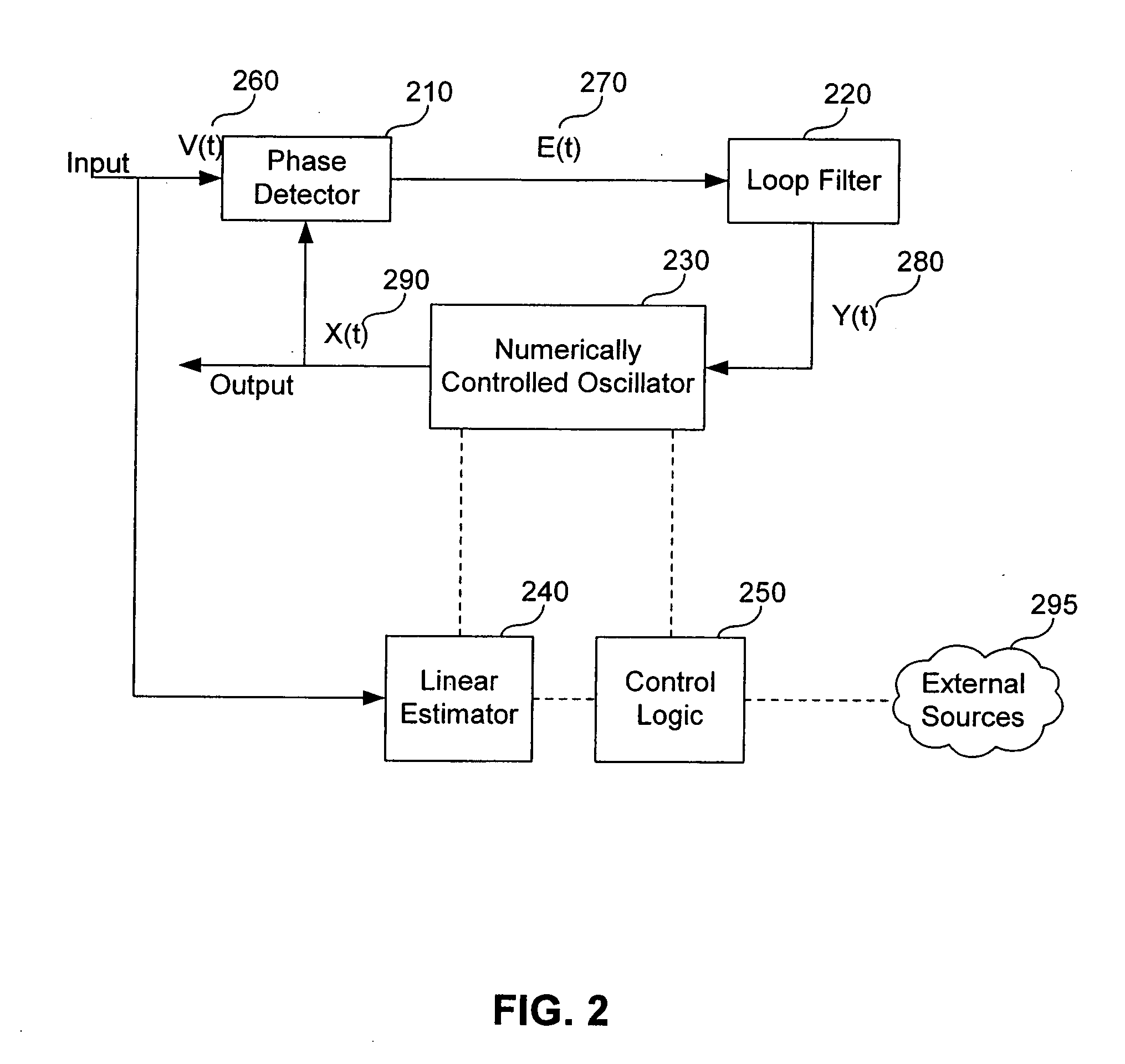
[0026]FIG. 2 illustrates timing recovery system 200, according to an embodiment of the invention. Timing recovery system 200 comprises phase detector 210, loop filter 220, numerically controlled oscillator 230, linear estimator 240 and control logic 250. The solid and dashed lines between these components represent electrical connections. Timing recovery system 200 may be used to quickly achieve clock synchronization between a first and second electronic device.

[0027] Control logic 250 and linear estimator 240 are electrically coupled to each other and...


PUM


Abstract

A timing recovery system and method for accelerated clock synchronization of remotely distributed electronic devices is provided. The system includes a phase locked loop, a linear estimator and control logic. The method includes sampling a clock signal received from an electronic device, applying a linear estimation technique to estimate the frequency and phase of the received signal and providing those estimates to a phase locked loop to accelerate the phase locked loop acquisition rate and secure signal lock quickly.

Description

CROSS REFERENCE TO RELATED APPLICATIONS [0001] This application is a continuation of U.S. application Ser. No. 10 / 294,661, filed Nov. 15, 2002, which is hereby incorporated by reference in its entirety.BACKGROUND OF THE INVENTION [0002] 1. Field of the Invention [0003] The present invention relates to clock synchronization of remotely distributed electronic devices, and more particularly, to accelerating the acquisition rate of a phase locked loop used in a timing recovery system [0004] 2. Background of the Invention [0005] In the last several years distributed computing and communications systems that rely on or provide high speed data communications have become nearly ubiquitous. Such systems may include, but are not limited to, broadband communication systems using cable modems, satellite communication systems, fiber to the home (FTTH) communications networks, and board-to-board interconnections in a myriad of electronic devices. [0006] In many of these systems, the clocks in rem...

Claims


Application Information

Patent Timeline
Patent Type & Authority Applications(United States)
IPC IPC(8): H04L7/00H03L7/10H04J3/06H04L29/06H04N7/56H04N7/62
CPCH03L7/10H03L2207/06H04J3/0638H04L69/28H04N7/56H04N21/4305H04J3/0664H03L7/103
Inventor MILLER, KEVINHEBSGAARD, ANDERS
Owner AVAGO TECH INT SALES PTE LTD
Learn More