Current fault detection for light emitters

a technology of light emitters and fault detection, applied in emergency protective arrangements, semiconductor lasers, instruments, etc., can solve problems such as fuse blowing and device labels that are eye safety hazards

Inactive Publication Date: 2007-01-11
AVAGO TECH ECBU IP (SINGAPORE) PTE LTD
View PDF4 Cites 18 Cited by
  • Summary
  • Abstract
  • Description
  • Claims
  • Application Information

AI Technical Summary

Benefits of technology

[0004] In accordance with an embodiment of the present invention, a device includes a light emitter, a current sensing resistance, a current generator, and detection circuitry. The current generator is connected to the light emitter and to the current sensing resistance. During a normal operating mode of the device, the current generator regulates current flow through the light emitter. In a test mode, the current generator regulates current flow through the current sensing resistance. The detection circuitry, during the test mode, detects when current flow through the current sensing resistance is outside an expected range.

Problems solved by technology

If the optical flux that can impinge on a user's eye exceeds the standard set out in IEC 60825-1, the device must be labeled an eye safety hazard.
When the bias current to a laser light emitter exceeds the eye safety requirement, the fuse blows.

Method used


Image

  • Current fault detection for light emitters
  • Current fault detection for light emitters
  • Current fault detection for light emitters

Examples


Embodiment Construction

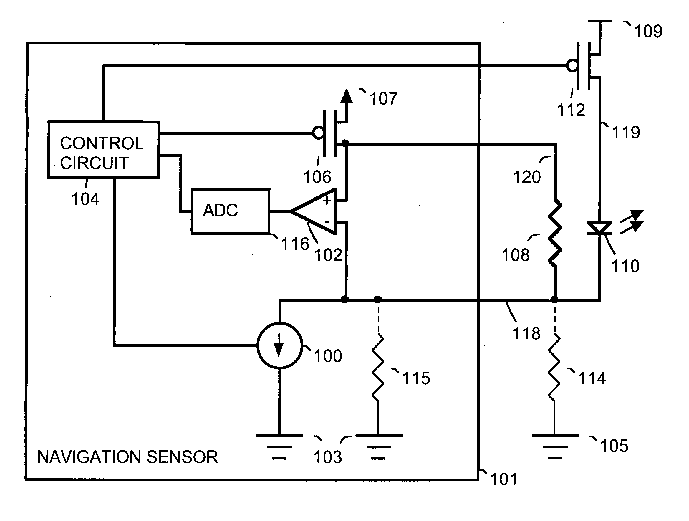
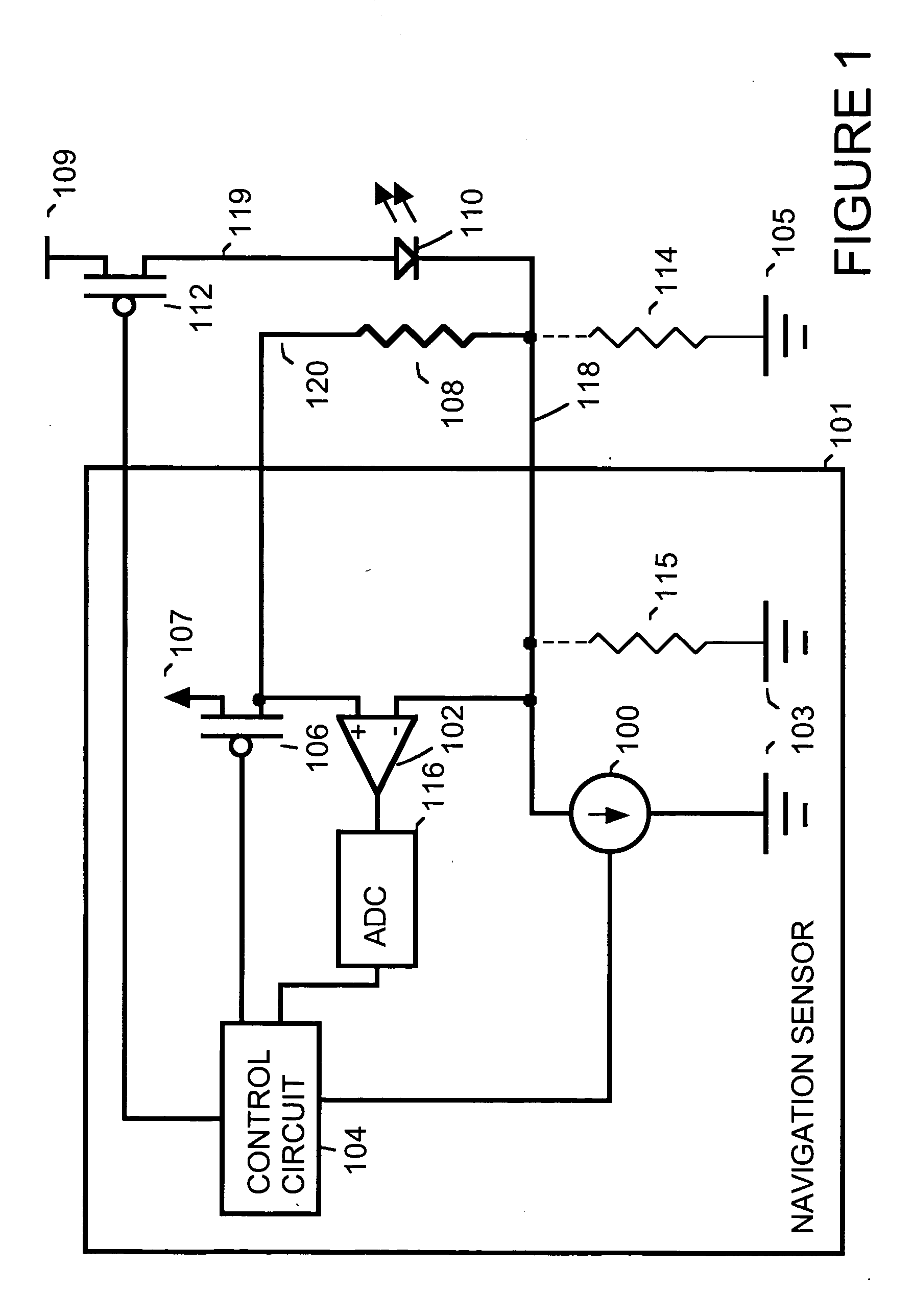
[0008]FIG. 1 is a simplified block diagram showing circuitry within a navigation sensor circuit 101 used to drive a light emitter 110. For example, navigation sensor circuit 101 is a navigation circuit such as those found on an optical mouse or other optical devices used for detection of motion. For example, navigation sensor circuit 101 is implemented as an integrated circuit. For example, light emitter 110 is implemented as a light emitting diode (LED), as a vertical-cavity surface emitting laser (VCSEL) or some other device that emits light.

[0009] Within navigation sensor 101, a programmable current source 100 regulates the current through light emitter 110 when a switch 112 is on. Current source 100 is connected, for example to a ground voltage 103 internal to navigation sensor 101. For example, switch 112 is implemented using a field effect transistor (FET).

[0010] A resistor 108 is a current sensing resistor used for detection of faults such as leakage resistance. A voltage v...


PUM


Abstract

A device includes a light emitter, a current sensing resistance, a current generator, and detection circuitry. The current generator is connected to the light emitter and to the current sensing resistance. During a normal operating mode of the device, the current generator regulates current flow through the light emitter. In a test mode, the current generator regulates current flow through the current sensing resistance. The detection circuitry, during the test mode, detects when current flow through the current sensing resistance is outside an expected range.

Description

BACKGROUND [0001] Products containing light emitting diodes (LEDs) or lasers that emit light in the visible or infrared range are required to conform to eye safety requirements in the International Electrotechnical Commission (IEC) standard 60825-1. If the optical flux that can impinge on a user's eye exceeds the standard set out in IEC 60825-1, the device must be labeled an eye safety hazard. This requirement applies not only during normal operation of the circuit, but also when predictable single faults occur in the circuit. [0002] Fuses can be used in a safety circuit for lasers. When the bias current to a laser light emitter exceeds the eye safety requirement, the fuse blows. Alternatively, a retriggerable transistor circuit can be used that shunts current away from a laser light emitter when the current exceeds a design threshold. [0003] Alternatively, a monitoring photodiode having an output indicative of the actual output of the laser can be used. For example, a comparator co...

Claims


Application Information

Patent Timeline
Patent Type & Authority Applications(United States)
IPC IPC(8): H02H9/08H01L33/00H05B44/00
CPCH01S5/06825H02H3/05H05B37/03H05B33/089H02H3/087H05B45/50H05B47/20G01R19/16528H02H3/08H02H11/005G01R19/165
Inventor MOYER, VINCENT C.BROSNAN, MICHAEL J.TAN, SHAN CHONG
Owner AVAGO TECH ECBU IP (SINGAPORE) PTE LTD
Why Eureka
Try Eureka