
Printing apparatus and printing position control method

a printing apparatus and position control technology, applied in the field of printing apparatus, can solve the problems of serial type ink jet printing apparatus including problems peculiar to itself, large device size, and generating a new negative effect, and achieve the effect of negative effect on an imag

Inactive Publication Date: 2007-01-11
CANON KK
View PDF1 Cites 11 Cited by
  • Summary
  • Abstract
  • Description
  • Claims
  • Application Information

AI Technical Summary

Benefits of technology

[0028] The present invention has been made in view of the foregoing problems and has an object of providing a method of adjusting a bidirectional registration such that a negative effect on an image such as “banding” is reduced as much as possible even when a printing head is slightly inclined.

Problems solved by technology

The line type printing apparatus can print at a high speed but the size of the device itself is likely to be large.
However, the serial type ink jet printing apparatus includes problems peculiar to itself.
Moreover, when multi-pass printing is adopted and a same image area of the printing medium is divided in the forward scanning and backward scanning for printing, another problem is generated.
However, according to the results obtained through the diligent examination by the inventors, even if the method described in Japanese Patent Application Laid-Open No. 7-81190 is adopted to adjust the bidirectional registration, when a slight inclination is included in the printing head, it has been confirmed that not only are the problems not solved sufficiently but also there is a case where a new negative effect is generated at the same time.
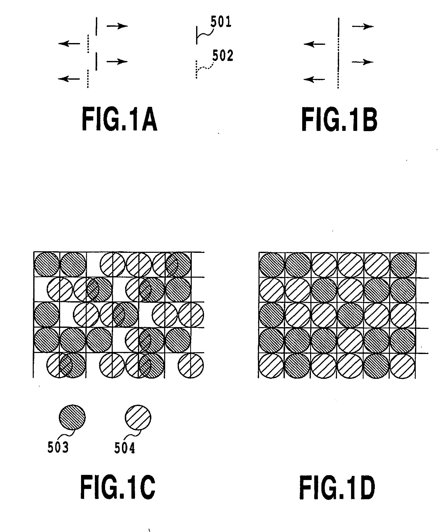
When the amount of displacement of the bidirectional registration is gradually increased, the complementary relationship between the dots printed in the forward scanning and the dots printed in the backward scanning becomes insufficient, and the extent becomes more remarkable as the amount of displacement is larger.
As a result of that, as the amount of displacement of the bidirectional registration becomes larger, the granularity is more deteriorated.
Also, in the state in which the printing head is inclined as in the example, areas of each of which a state of density variations is different as in the area A and the area B explained in FIG. 4A are arranged alternately in the sub-scanning direction and thus, it is likely to deteriorate the extent of banding.
However, in the bidirectional registration adjustment pattern printed in such a method, the extent of the banding generated by the effect of the head inclination can not be identified.
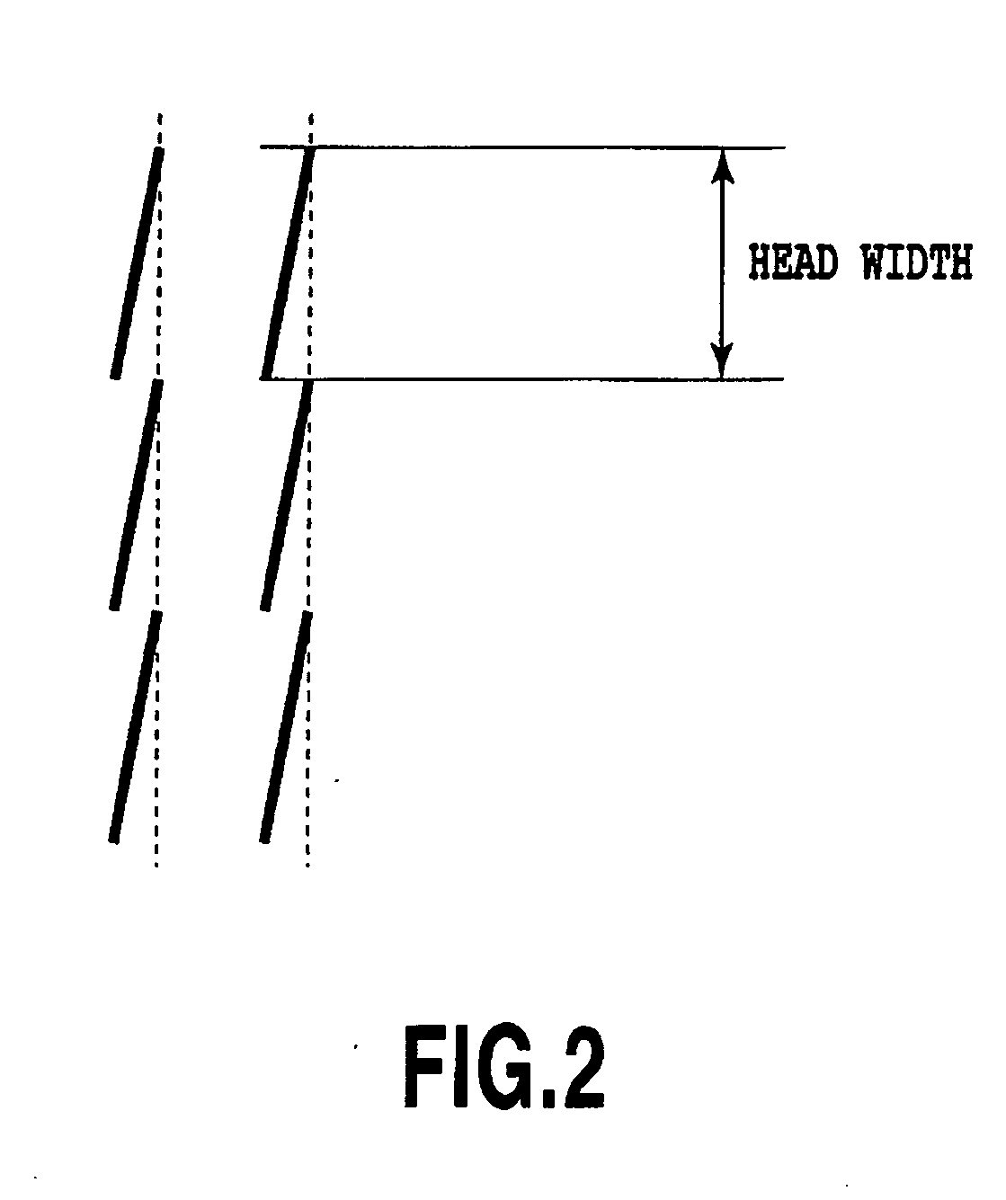
However, as explained above, when the printing head is inclined, even when the bidirectional registration displacement is approximately ±1 pixel, the banding is easily identified, which as a result deteriorates the image quality.
In particular, as visual characteristics of human beings, a band-shaped repetition as shown in banding rather than uniform roughness shown in granularity is felt to be uncomfortable in more cases.
Also from such a reason, reducing the banding described above is a very important challenge.

Method used


Image

  • Printing apparatus and printing position control method
  • Printing apparatus and printing position control method
  • Printing apparatus and printing position control method

Examples


embodiment 1

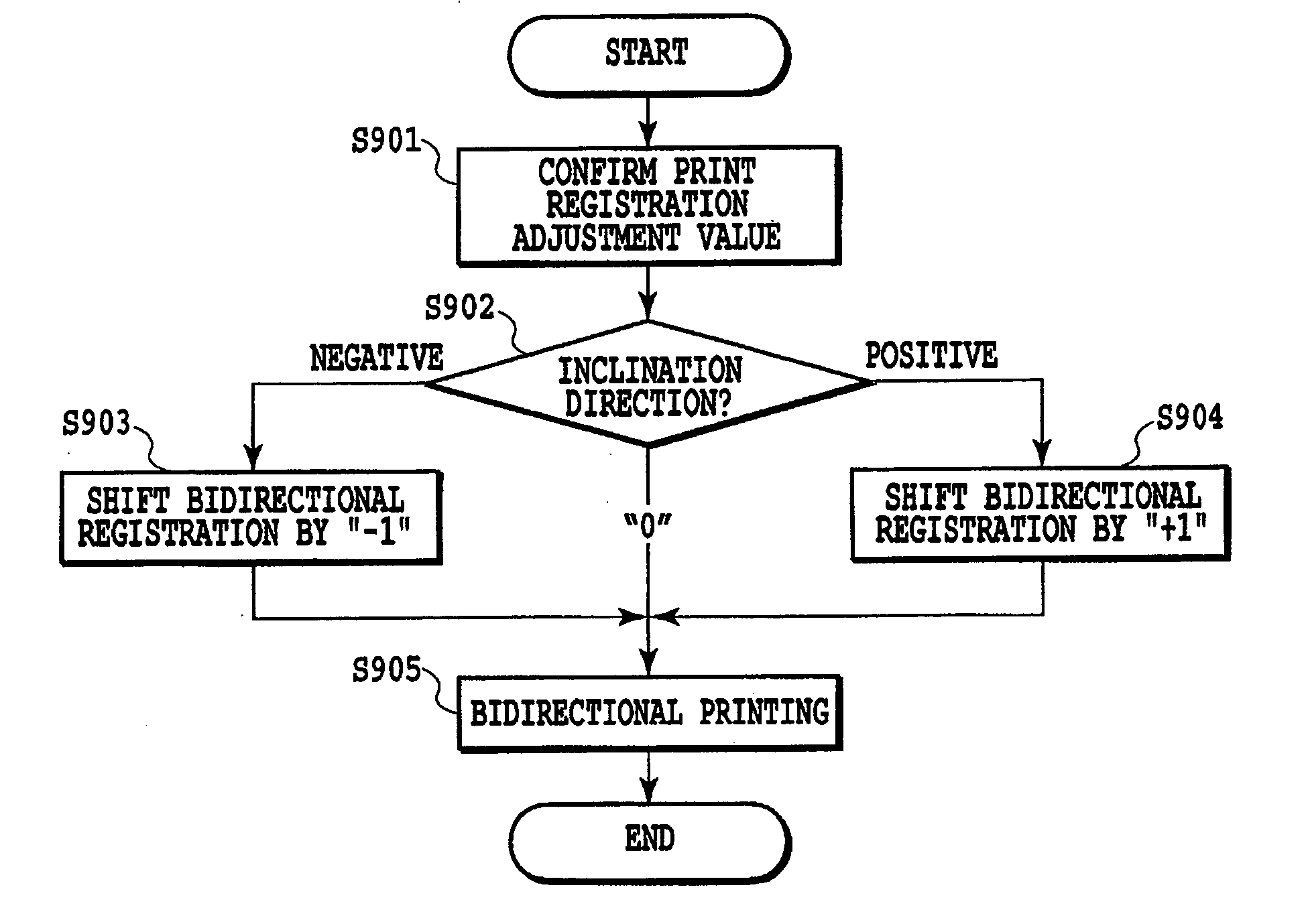
[0066]FIG. 9 is a flow chart for explaining each process when a bidirectional registration adjustment mode of the embodiment is carried out. When the process is started, firstly in step S801, the CPU 100 reads pattern data for bidirectional registration adjustment which is stored in the ROM 101 to output this to the printing medium through various types of drive means. The adjustment pattern printed at the time is arranged that while the amount of displacement of the bidirectional registration is fluctuated step by step, a plurality of patterns are simultaneously printed in parallel, which enables the user to select an optimum pattern from the plurality of patterns. Moreover, in the pattern of the embodiment, a pattern to distinguish an inclination direction of the printing head is also printed simultaneously.

[0067] In the following step S802, the user inputs a selected pattern and a determined inclination direction of the printing head. An input method may be a method of the direc...

embodiment 2

[0077] A second embodiment of the present invention will be explained in the following. In the embodiment, the printing apparatus shown in FIG. 6 and FIG. 8 is also applied, but furthermore in the embodiment, the printing apparatus includes means and a configuration possibly to detect a pattern automatically and set an adjustment value without depending on the visual determination by the user.

[0078] In recent years, some of the ink jet printing apparatuses adopt a technology to correct the inclination of the printing head so as to reduce negative effects on the image by the inclination of the printing head mentioned above for being provided. The inclination correction technology is a technology in which the timing to eject according to a data in each printing element within the printing head is shifted relatively so as to form, for instance, the ruled line as shown in FIG. 2 into a straight line, in a serial type printing apparatus. As a method to shift the ejection timing, a metho...


PUM


Abstract

A method of adjusting bidirectional registration to reduce negative effects on the image such as “banding” even if bidirectional registration includes a slight amount of displacement is provided. For that purpose, correction is applied to a first adjustment value for adjusting a bidirectional registration displacement in response to an extent of inclination of a printing head to obtain a second adjustment value. Then a bidirectional printing is performed with timing adjusted on the basis of the second adjustment value. As a result of that, even if there is a slight variation in an adjustment value of the bidirectional registration and the inclination of the printing head, the banding generated by this can be reduced as much as possible.

Description

BACKGROUND OF THE INVENTION [0001] 1. Field of the Invention [0002] The present invention relates to a printing apparatus which applies a printing agent on a printing medium from printing means with a plurality of printing elements arranged therein to form an image. In particular, the present invention relates to a method and a configuration for adjusting a printing position displacement of the printing element. [0003] 2. Description of the Related Art [0004] A printing apparatus having a function of a printer, a copier or a facsimile, or a printing apparatus used as an output device of a composite electronic device including a computer or a word processor or a workstation prints an image on a printing medium such as a paper or a thin plastic sheet based on image information (including character information). Such printing apparatuses can be classified into an ink jet type printing apparatus, a wire dot type printing apparatus, a thermal type printing apparatus or a laser beam type ...

Claims


Application Information

Patent Timeline
Patent Type & Authority Applications(United States)
IPC IPC(8): B41J29/393
CPCB41J29/393B41J2/1752B41J19/145
Inventor KAWATOKO, NORIHIROHAYASHI, MASASHICHIKUMA, TOSHIYUKIKANDA, HIDEHIKO
Owner CANON KK
Learn More