
Layered manufactured articles having small-width fluid conduction vents and methods of making same

Inactive Publication Date: 2007-01-11
THE EX ONE +1
View PDF8 Cites 16 Cited by
  • Summary
  • Abstract
  • Description
  • Claims
  • Application Information

AI Technical Summary

Benefits of technology

[0008] One aspect of the present invention is to provide a method of producing articles that contain at least one small-width fluid conduction vent which avoids one or more of the drawbacks inherent in the prior art. To this end, the present invention utilizes a layered manufacturing process to produce an article having at least one small-width fluid conduction vent wherein the vent or vents are produced during the layered manufacturing process.
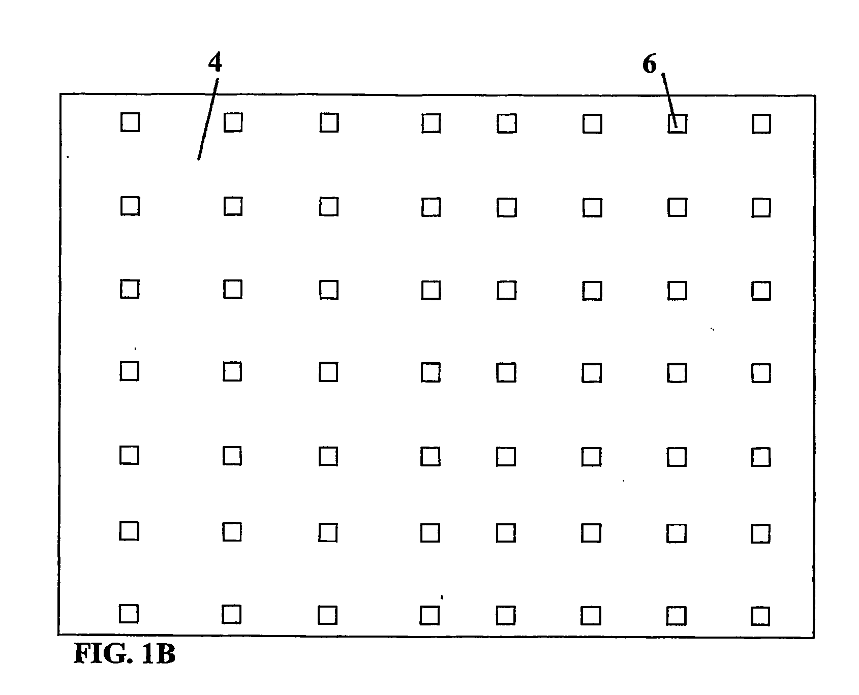
[0012] In contradistinction to the prior art, the present invention gives the article designer the freedom to locate the small-width fluid conduction vent or vents wherever they are most needed without resort to sectioning and reassembling the article. The present invention also permits the article designer to optimize both the orientation of the vent or vents and the placement density of multiple vents. For example, the present invention allows the designer to orient the vents of an EPS bead mold parallel to the mold's opening direction to facilitate the easy removal of the formed EPS part and reduce the likelihood of vent blockage by EPS material that might extrude into a vent. The present invention also permits the designer to use a high placement density of vents in areas needing a large amount of ventilation while using a lower placement density of vents in areas needing less ventilation. Moreover, the flexibility provided by the present invention permits the designer to use a computer-run algorithm to optimize vent design, placement, and array density. The computer program containing the algorithm may even create an electronic file incorporating the vents into the article and cause the article to be printed, all with little or no human intervention after the design criteria have been selected.
[0013] Furthermore, while most perforation techniques restrain the designer to the use of a small-width fluid conduction vent or vents having round cross-sections, the present invention allows the designer to use a wide variety of cross-sectional shapes, even square. The present invention also permits the designer to vary both the cross-sectional shape and / or the width of a vent along its length. It also frees the designer from the prior art's constraint that the vent center line must be straight and that it be of a length that is solely dependent on the article's thickness. Instead, the present invention permits the designer to turn, curve or otherwise redirect the center line. The great flexibility provided by the present invention with regard to a vent's cross-sectional shape, width, length, orientation, and center line curvature taken alone or in combination with the ease at which the present invention allows vents to placed at any desired location and in any array density provides unprecedented opportunities for the designer to use vent design as a means of fluid and pressure control.

Problems solved by technology

Such vent-making processes are costly and time consuming.
Moreover, they restrict the placement of vents to areas that are accessible to the tool that will be used for making the vent.
Another drawback of the prior art is that the orientation of the small-width fluid conduction vents with respect to the article surface is restricted by the perforation technique employed and the accessibility of the portion of the surface at which an individual small-width fluid conduction vent is to be placed.
Where the surface shape curves or is complex or access is limited, the small-width fluid conduction vent is likely to have a less-than-optimal orientation.
Another drawback of the prior art is that it restricts the vent or vents to having substantially straight center line and most prior art methods are limited to producing vents having substantially round cross-sectional shapes.

Method used


Image

  • Layered manufactured articles having small-width fluid conduction vents and methods of making same
  • Layered manufactured articles having small-width fluid conduction vents and methods of making same
  • Layered manufactured articles having small-width fluid conduction vents and methods of making same

Examples


Embodiment Construction

[0022] In this section, some presently preferred embodiments of the present invention are described in detail sufficient for one skilled in the art to practice the present invention. It is to be understood, however, that the fact that a limited number of presently preferred embodiments are described herein does not in any way limit the scope of the invention as set forth in the appended claims.

[0023] For clarity of illustration and conciseness, the description of presently preferred embodiments is limited to the description of making EPS bead molds wherein the layered manufacturing process employed is the 3DP process. Persons skilled in the art will recognize that the present invention includes the making of any type of article having one or more small-width fluid conduction vents which is within the size and material capability of any layered manufacturing process that is adaptable to the inclusion of one or more small-width fluid conduction vents in the article as it is being bui...


PUM

PropertyMeasurementUnit
Lengthaaaaaaaaaa
Shapeaaaaaaaaaa
Widthaaaaaaaaaa

Abstract

The invention utilizes a layered manufacturing process to produce an article (2) having at least one small-width fluid conduction vent (6) produced during the layered manufacturing process. Such small-width fluid conduction vents (6) may have any desirable cross-sectional shape, orientation, and curvature. The invention also includes articles (2) containing at least one small-width fluid conduction vent (6) wherein the article (2) and the small-width vent or vents (6) are simultaneously produced by a layered manufacturing process.

Description

TECHNICAL FIELD [0001] The present invention relates to layered manufactured articles which contain at least one small-width fluid conduction vent. More specifically, the present invention relates to such articles wherein at least one such vent is produced during the layered manufacturing process. Still more specifically, the present invention relates to such articles wherein the vent or vents have varying shape or a non-straight center line. The present invention also relates to methods for making such articles. BACKGROUND ART [0002] Many articles of manufacture contain small-diameter fluid conduction vents which permit fluid to flow into and / or out of the article or a portion of the article. For example, molds for making articles from expanded polymer beads like expanded polystyrene (“EPS”) contain a plurality of small-width fluid conduction vents for conducting steam into or through the mold for causing the polymer beads to further expand and bond together. Injection molding mold...

Claims


Application Information

Patent Timeline
IPC IPC(8): B29C35/08B22F3/00B22F3/105B22F5/00B29C33/10B29C33/38B29C45/34B29C51/36B29C67/00
CPCB22F3/008B22F3/1055B29C67/0081B29C67/0051B29C51/36B29C45/34B29C33/3842B22F2998/10B29C33/10C22C1/0475B22F3/26B29C64/165B29K2105/048B33Y70/00B33Y80/00Y02P10/25B22F10/28B22F10/14B22F10/80
Inventor RYNERSON, MICHAEL L.HETZNER, JAMESFISHER, JUDITH L.MAAS, DANIEL J.NELSON, DONALD R.VOSS, LAWRENCE J.
Owner THE EX ONE
Learn More