Modular area wall

a technology of modular parts and area walls, applied in the field of modular area walls, can solve the problems of unwieldy transportation of large area wall assemblies to the jobsite, high cost, and large storage space, and achieve the effects of easy manufacturing construction, easy assembly, and easy assembly

Inactive Publication Date: 2007-01-11
THEOPHILUS MORGAN
View PDF28 Cites 4 Cited by
  • Summary
  • Abstract
  • Description
  • Claims
  • Application Information

AI Technical Summary

Benefits of technology

[0010] In an advantage provided by the present invention, a modular area wall section is provided which eliminates the need for maintaining a large plurality of area wall heights in stock.
[0012] In an advantage provided by the present invention, a modular area wall system is provided which eliminates problems associated with aligning holes in attachment fins of modular area wall sections.
[0014] In an advantage provided by the present invention, a modular area wall system is provided with a strong and lightweight construction.

Problems solved by technology

Maintaining a large stock of area walls of various heights is not only expensive, but requires a very large amount of storage space.
One drawback associated with constructing the assemblies at the factory includes the unwieldiness associated with transporting a large area wall assembly to the jobsite.
Another drawback is the inability to adjust the area wall on site and / or construct a replacement, should the original become damaged.
One drawback associated with constructing the area wall on sight includes the difficulty in aligning the sections while working below grade.
Not only is it difficult to hold the sections in alignment while fastening them together, it is also difficult to avoid coupling the sections together at a cant, with one side having more overlap than the other.
An additional drawback associated with constructing area walls on site is trying to align the holes of an attachment fin on one section with the holes of the attachment fin on the other section.
The difficulty and time associated with making all of the appropriate alignments adds additional cost and delay to the area wall installation.
Another drawback associated with prior art area walls is the cost associated with providing customized corrugations and thicker panels to add strength to the area walls.
While it would be desirable to use thinner standard sinusoidal corrugation for the area walls, which would not only be lighter but also cheaper, the difficulty encountered in the prior art heretofore has been that such standard corrugation material has been found to lack the requisite strength to adequately hold back the backfill from the window.

Method used


Image

  • Modular area wall
  • Modular area wall
  • Modular area wall

Examples


Embodiment Construction

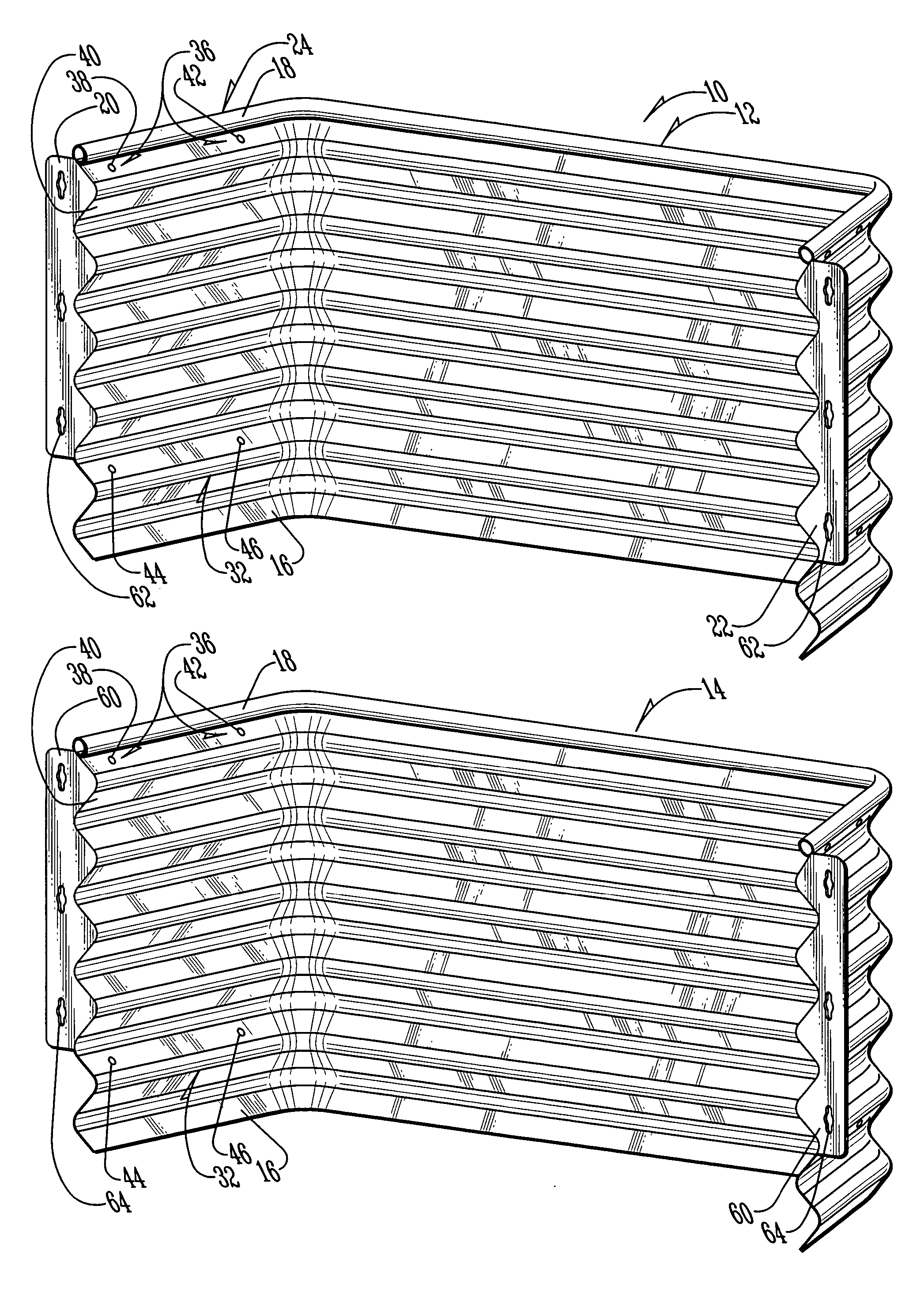
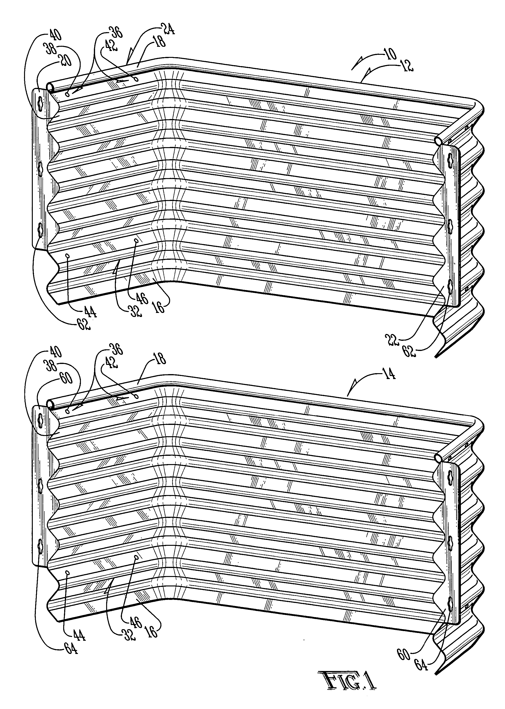
[0022] The area wall system of the present invention is shown generally as (10) in FIG. 1. The system (10) includes a first area wall section (12) and a second area wall section (14). Although the area wall sections may be constructed of any material known in the art, in the preferred embodiment, the area wall sections (12) and (14) are constructed of corrugated, galvanized steel having a substantially sinusoidal cross-section in a manner such as that known in the art.

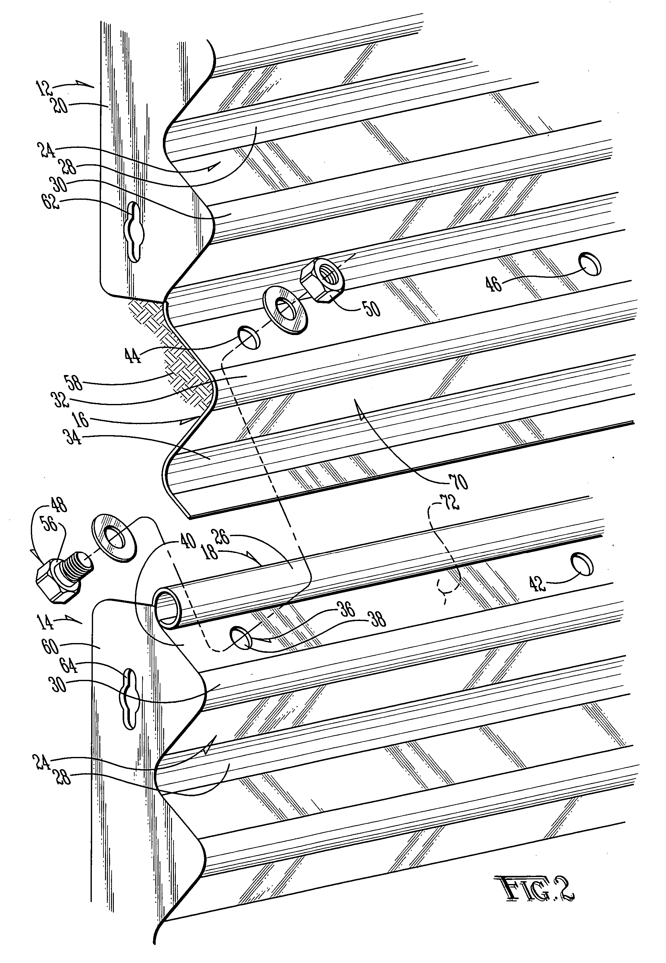
[0023] As shown in FIG. 1, the first area wall section (12) and second area wall section (14) are similar in design, each being provided with a lower connection plate (16) and an upper strengthening rib (18). Each area wall section (12) and (14) is also provided with a first attachment fin (20) and second attachment fin (22). The attachment fins (20) and (22) are preferably welded or otherwise secured to the area wall sections (12) and (14). The attachment fins (20) and (22) preferably extend to a point at least one i...


PUM


Abstract

A modular area wall system for constructing area wall assemblies at a jobsite. The area wall system provides modular sections of varying heights, each provided with a connection plate and a strengthening rib to allow them to be connected to one another in a simple and secure manner. By providing the strengthening rib in overlapping engagement with another area wall section, lighter material of more inexpensive construction may be utilized to reduce the overall cost and weight of the resulting assembly. The system may also be used with sections of varying depth to create a tiered area wall, using teachings of the present invention.

Description

BACKGROUND OF THE INVENTION [0001] 1. Field of the Invention [0002] The invention relates in general to a modular area wall system and, more particularly, to an area wall system which is of a lightweight, modular, inexpensive construction, yet is sturdy and adaptable to projects of varying depths below grade. [0003] 2. Description of the Prior Art [0004] It is known in the art to provide area walls around windows located below grade. The walls provide for the ingress of light and the egress of persons in the event of a fire. Although poured concrete and masonry area walls are known in the art, the preferred method of protecting below-grade windows from backfill and the like is preformed, galvanized metal area walls having a generally C-shaped cross-section. Given the different depths of windows below grade, area walls of various sizes must be employed. Maintaining a large stock of area walls of various heights is not only expensive, but requires a very large amount of storage space....

Claims


Application Information

Patent Timeline
IPC IPC(8): E04F17/06
CPCE04F17/06
Inventor THEOPHILUS, MORGAN
Owner THEOPHILUS MORGAN
Why Eureka
Try Eureka