
Digital wireless basestation

a wireless basestation and wireless technology, applied in the field of digital wireless basestations, can solve the problems of difficult for rf suppliers with highly specialised analogue design skills to develop products, and achieve the effect of high efficiency

Inactive Publication Date: 2007-01-04
RADIOSCAPE
View PDF2 Cites 120 Cited by
  • Summary
  • Abstract
  • Description
  • Claims
  • Application Information

AI Technical Summary

Benefits of technology

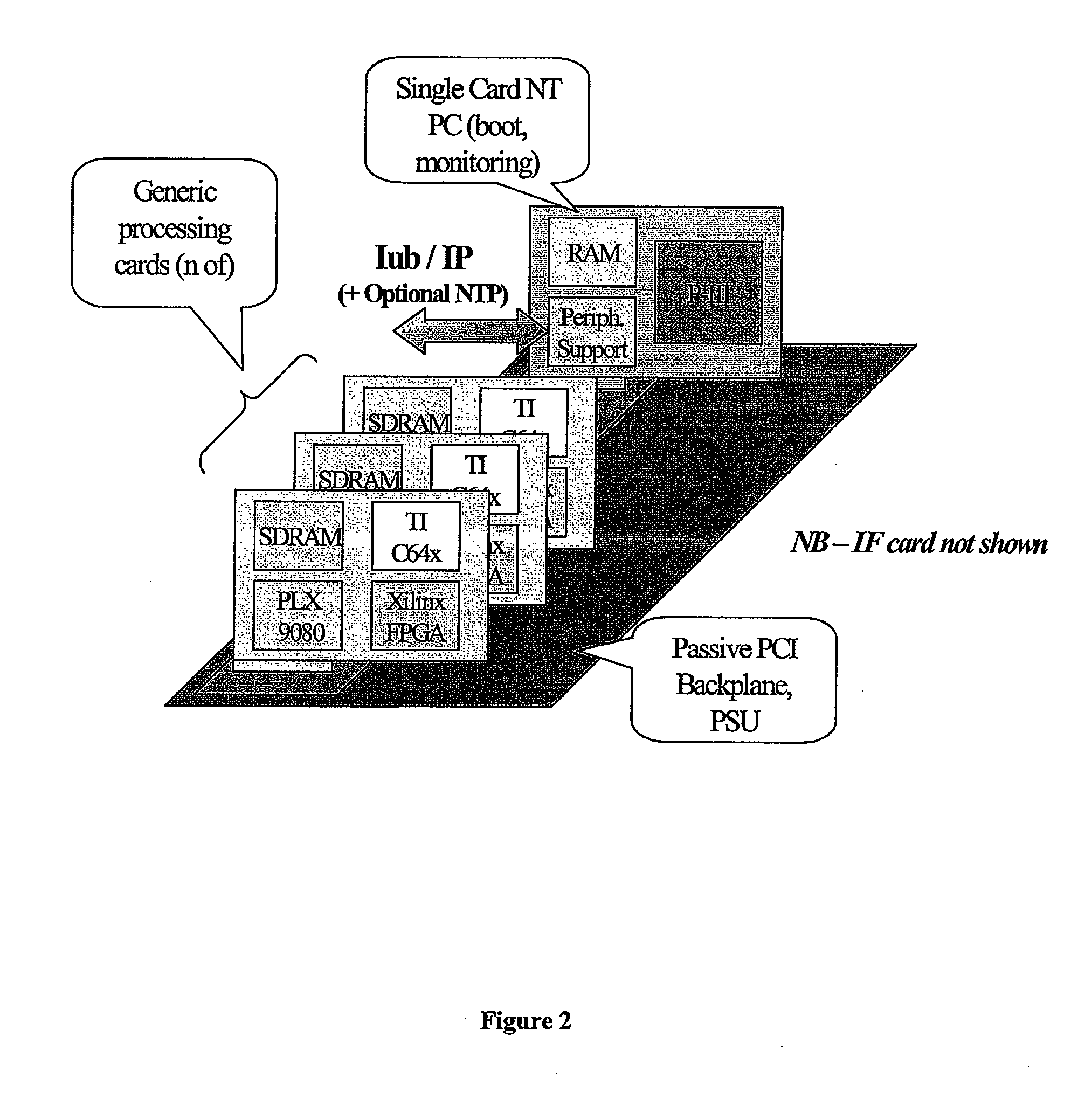
[0007] In one implementation of the present invention, commodity protocols and hardware are utilised to turn the basestation, (conventionally a highly expensive, vendor-locked, application specific product), into a generic, scalable baseband platform, capable of executing many different modulation standards with simply a change of software. IP is used to connect this device to the backnet, and IP is also used to feed digitised IF to and from third party RF modules, using an open data and control format. This approach—focussing on moving the basestation into the software arena using commodity hardware, decomposition and open standards, promises to provides great benefits, whilst in the same time significantly reducing the inherent technology risk involved in taking up new communications protocols. These general principles can be enlarged upon as follows: In an implementation, the hardware abstraction layer runs on hardware comprising a PCI-bus backplane. The use of the industry standard 32 bit×33 MHz PCI-backplane makes available: (i) a wide range of sophisticated and low cost devices (such as bus-mastering DMA bridge chips), previously restricted to the PC domain; (ii) the PC as a development platform (with its wide range of development tools and peripheral support); and makes the PC available as a remote monitoring platform. The hardware elements within the virtual machine may communicate using an appropriate, architecture neutral messaging system. For example, 120 compliant messaging may be used: the use of an industry wide messaging exemplifies the general approach of the present invention away from closed, proprietary systems, to open systems which can many different suppliers can develop for.
[0014] An implementation also uses standard IP based protocols: the basestation sends an IP-based digital IF feed to a radio mast. The IP feed is fed up to multiple RF units and the IP feed derived from a signal received at the mast can be passed down to multiple processor boards. Using standard IP based protocols makes available a broad range of IP based components and expertise, lowering costs and facilitating third party design contributions. In one preferred implementation, bus LVDS (low voltage differential signalling) is used as the underlying bearer for the data component sent to and from the RF ‘heads’, supporting the RTP / UDP / IP protocols over this bearer. In another implementation, a fibre optic bearer (such as FiberChannel) is used as the bearer. Use of fibre optic bearers becomes more attractive as the distance between the basestation proper and the RF heads increases, and as the IF bandwidth increases (either as a result of a higher IF nominal centre frequency, or as an increase in the number of bits used in the ADC / DACs, or a combination of both of these factors).
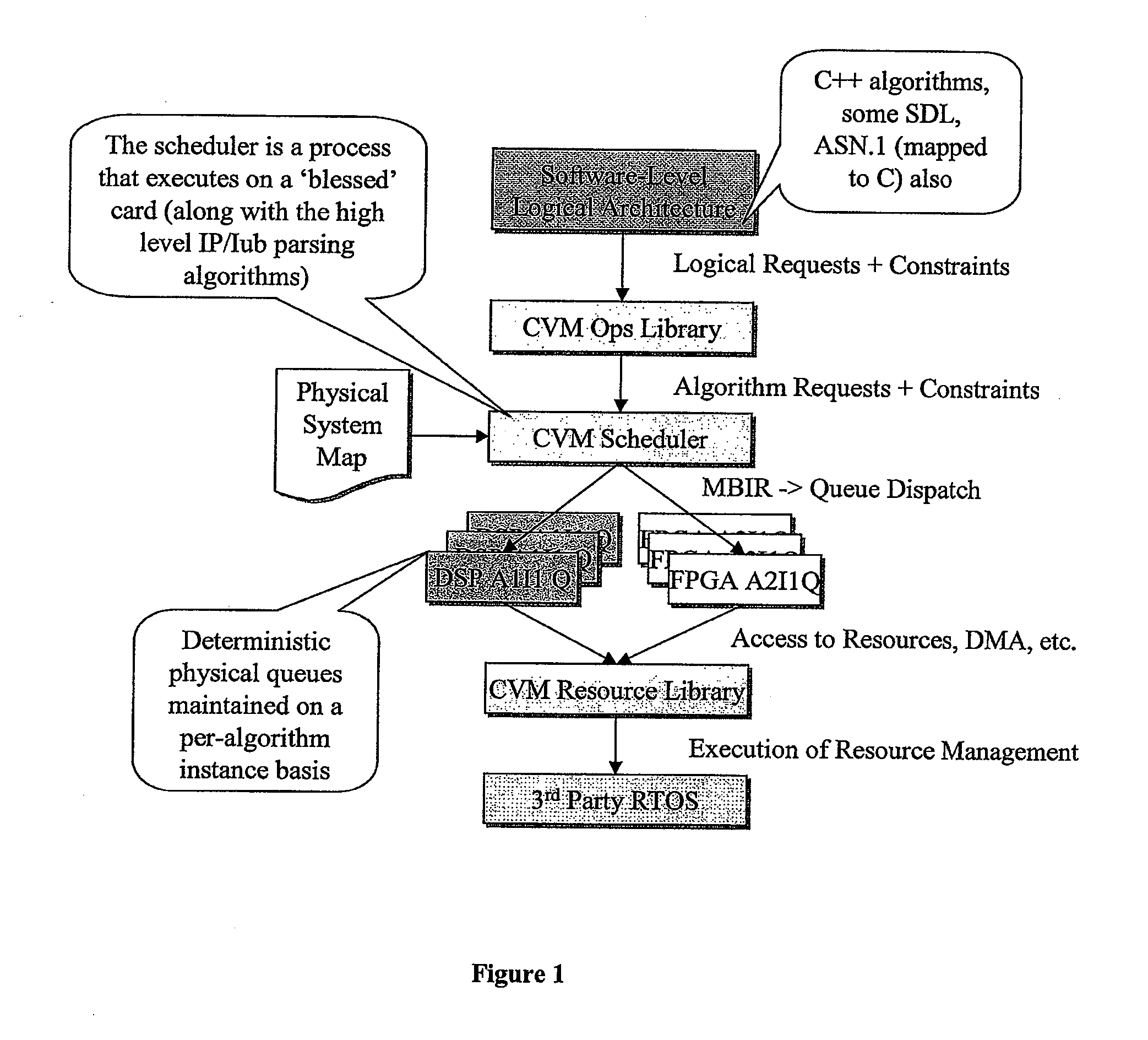
[0019] An implementation of the virtual machine hardware layer is called the CVM (Communications Virtual Machine). The CVM is both a platform for developing digital signal processing products and also a runtime for actually running those products. The CVM in essence brings the complexity management techniques associated with a virtual machine layer to real-time digital signal processing by (i) placing high MIPS digital signal processing computations (which may be implemented in an architecture specific manner) into ‘engines’ on one side of the virtual machine layer and (ii) placing architecture neutral, low MIPS code (e.g. the Layer 1 code defining various low MIPS processes) on the other side. More specifically, the CVM separates all high complexity, but low-MIPs control plane and data ‘operations and parameters’ flow functionality from the high-MIPs ‘engines’ performing resource-intensive (e.g., Viterbi decoding, FFT, correlations, etc.). This separation enables complex communications baseband stacks to be built in an ‘architecture neutral’, highly portable manner since baseband stacks can be designed to run on the CVM, rather than the underlying hardware. The CVM presents a uniform set of APIs to the high complexity, low MIPS control codes of these stacks, allowing high MIPS engines to be re-used for many different kinds of stacks (e.g. a Viterbi decoding engine can be used for both a GSM and a UMTS stack).
[0022] During actual operation, a scheduler in the CVM can intelligently allocate tasks in real-time to computational resources in order to maintain optimal operation. This approach is referred to as ‘2 Phase Scheduling’ in this specification. Because the resource requirements of different engines can be (i) explicitly modelled at design time and (ii) intelligently utilised during runtime, it is possible to mix engines from several different vendors in a single product. As noted above, these engines connect up to the Layer 1 control codes not directly, but instead through the intermediary of the CVM virtual machine layer. Further, efficient migration from the PCT non-real time prototype to a run time using a DSP and FPGA combination and then onto a custom ASIC is possible.
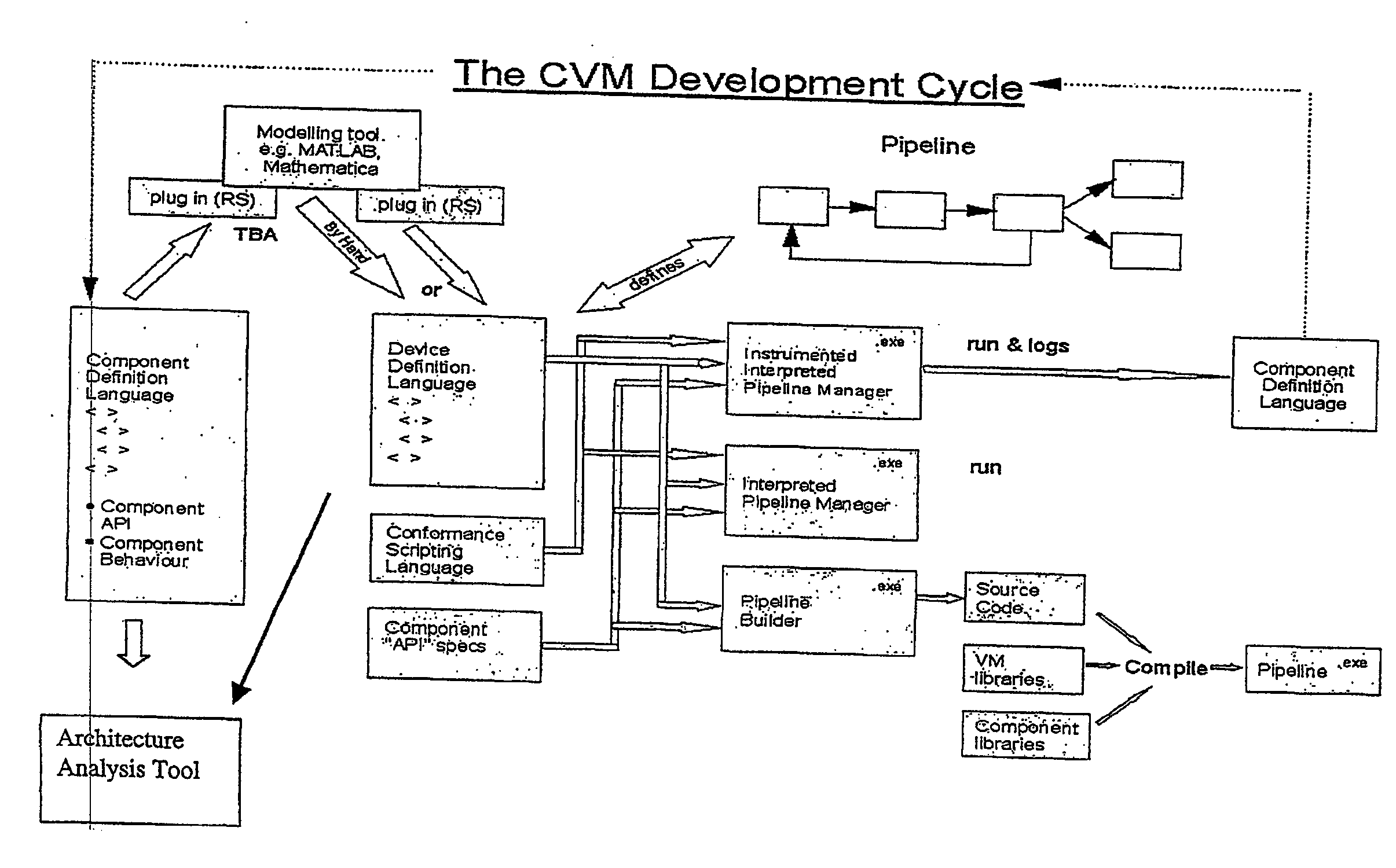
[0028] In one implementation of the invention, there is a design tool for simulating the baseband stack of the second aspect, in which the design tool can link together software and hardware components using a number of standard connection types and synchronisation methods which enable the management of a pipeline to be determined by the data processed by the pipeline. The design tool can support stochastic simulation of load on multiple parallel datapaths (distribution to underlying ‘engines’ of the virtual machine) where the effect of the distribution of these datapaths to different positions within a non-symmetric memory topology (e.g., some components being local, others accessible across a contested bus, etc) may be explored with respect to expected loading patterns for given precomputed scenarios of use. The output of such a design tool is an initial partitioning of the design ‘engines’ (high-MIPs components) into variously distributed ‘hard’ and ‘soft’ datapaths (where a hard datapath is a flow implemented in an ASIC or FPGA, and soft datapath is a flow implemented over a conventional programmable DSP). This partitioning is visible to the dynamic scheduling engine (by means of which the high level, architecture neutral software dispatches its processing requests to the underlying engines) and is utilised by it, to assist in the process of making optimal or close to optimal runtime scheduling decisions.

Problems solved by technology

Previously, closed, proprietary interfaces have been the norm; these make it difficult for RF suppliers with highly specialised analogue design skills to develop products, since to do so requires a knowledge of complex and fast changing digital basestation design.

Method used


Image

  • Digital wireless basestation
  • Digital wireless basestation
  • Digital wireless basestation

Examples


Embodiment Construction

[0043] The present invention will be described with reference to an implementation from RadioScape Limited of London, England of a software defined radio (“SDR”) basestation, running over a Generic Baseband Processor (“GBP™”). The basestation is a UMTS node-b. As noted above, the essence of the RadioScape approach is to use commodity protocols and hardware to turn a basestation, previously a highly expensive, vendor-locked, application specific product, into a generic, scalable baseband platform, capable of executing many different modulation standards with simply a change of software. In the RadioScape system, IP is used to connect this device to the backnet, and IP is also used to feed digitised IF to and from third party RF modules, using an open data and control format.

[0044] The SDR-based UMTS node-b basestation is a software description (in C++, DSP assembler and Handel-C / VHDL) running over the GBP. The GBP is a powerful hardware platform designed to provide the MIPs and thro...


PUM


Abstract

A digital wireless basestation is disclosed which is programmed with a hardware abstraction layer suitable for enabling one or more baseband processing algorithms to be represented using high level software. Commodity protocols and hardware turn a basestation, previously a highly expensive, vendor-locked, application specific product, into a generic, scalable baseband platform, capable of executing many different modulation standards with simply a change of software. IP is used to connect this device to the backnet, and IP is also used to feed digitised IF to and from third party RF modules, using an open data and control format.

Description

CROSS-REFERENCE TO RELATED APPLICATIONS [0001] This application is a continuation of U.S. application Ser. No. 10 / 182,043, filed Jul. 24, 2002, which claims the priority of PCT Application No. PCT / GB01 / 00280 filed 24 Jan. 2001; British application GB 0030698.5 filed 15 Dec. 2000; and British application GB 0001577.6 filed 24 Jan. 2000.FIELD OF THE INVENTION [0002] This invention relates to a digital wireless basestation. A basestation is a transceiver node in a radio communications system, such as UMTS (Universal Mobile Telephony System). Conventionally, one basestation communicates with multiple user equipment (UE) terminals. The term ‘communicates’ and ‘communication’ covers one-way communication (e.g. a radio broadcast), two way (e.g. UMTS) and can be one to one and one to many. DESCRIPTION OF THE PRIOR ART [0003] Digital signal processing in a digital wireless communications basestation is characterised by wide (i.e. highly parallel) algorithms with low latencies, high numerical...

Claims


Application Information

Patent Timeline
Patent Type & Authority Applications(United States)
IPC IPC(8): G06F17/50H04B7/26G06F9/46H04B1/38H04B1/40H04B7/00H04L12/28H04L12/56H04L29/06H04M1/00H04W80/00H04W88/08H04W88/10
CPCH04B1/0003H04B1/406H04L29/06H04W80/00H04L69/06H04W88/10H04L69/16H04L69/161H04W88/08
Inventor FERRIS, GAVIN ROBERT
Owner RADIOSCAPE
Learn More