
Two-stage screw compressor

a compressor and screw technology, applied in the direction of positive displacement liquid engines, piston pumps, liquid fuel engines, etc., can solve the problems of increased cast weight, affecting the performance of the compressor, and not taking into account the increase in noise, so as to prevent internal resonance and reduce noise.

Inactive Publication Date: 2007-01-04
HITACHI APPLIANCES INC
View PDF7 Cites 15 Cited by
  • Summary
  • Abstract
  • Description
  • Claims
  • Application Information

AI Technical Summary

Benefits of technology

[0006] An object of the present invention is to prevent internal resonance occurring in a discharge casing by means of a simple structure, and thereby realize reduction in noise, in a two-stage screw compressor as described above.
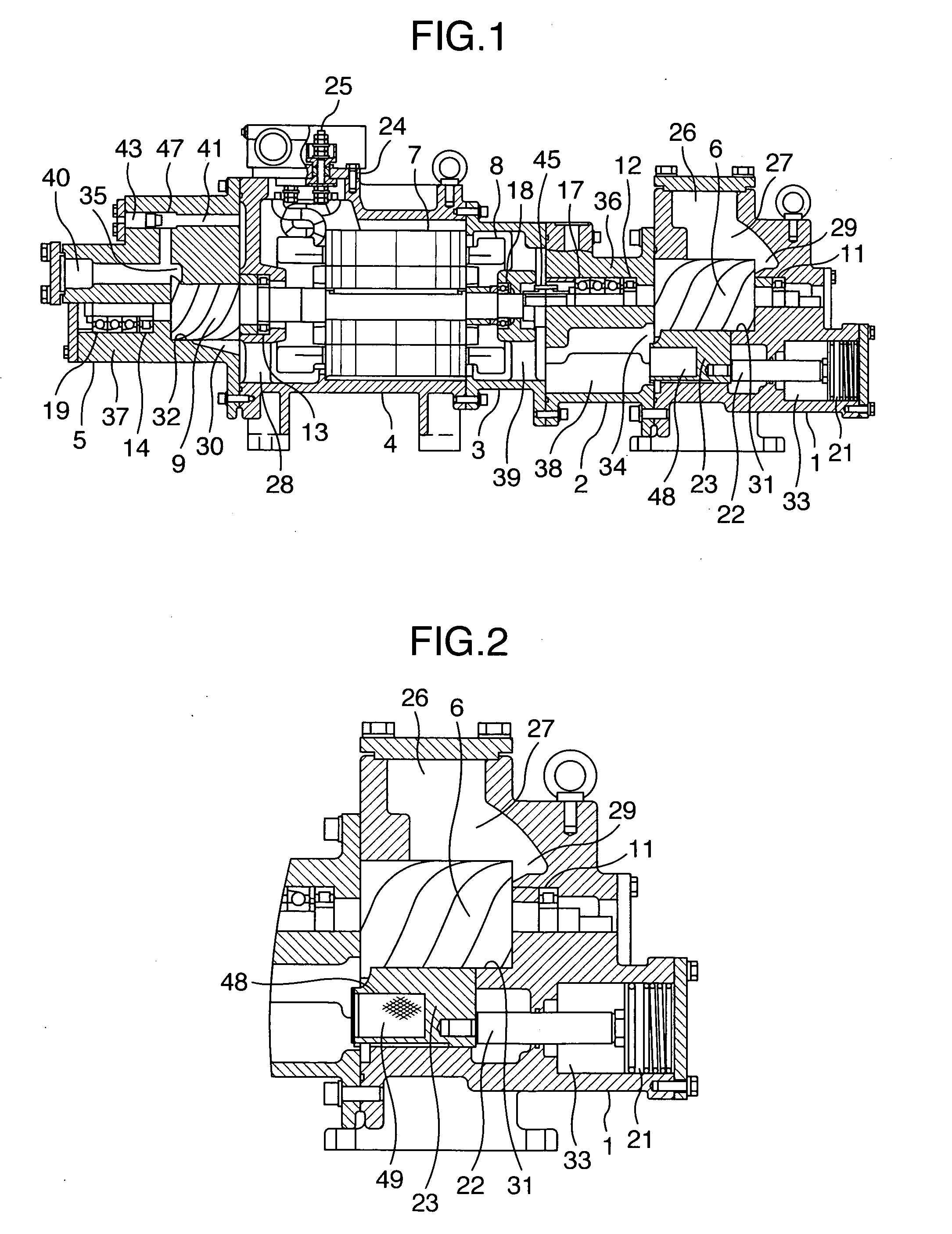
[0007] In order to achieve the above-described object, the present invention provides a two-stage screw compressor including: a low pressure stage casing for accommodating a low pressure stage compression mechanism and a bearing member, which low pressure stage casing is provided with a capacity control part constituted by a slide valve, a rod and a piston; a discharge casing provided on a discharge side of the aforesaid low pressure stage casing for accommodating a bearing member supporting the low pressure stage compression mechanism; a high pressure stage casing for accommodating a high pressure stage compression mechanism and a bearing member; and an intermediate stage casing for connecting the aforesaid discharge casing and the aforesaid high pressure stage casing, and accommodating an electric motor, wherein a cavity is formed on a discharge casing side in the slide valve so as to enlarge the capacity of a discharge space formed in the aforesaid discharge casing, so that internal resonance occurring in the discharge casing is prevented.
[0008] In this case, by making the length in an axial direction of the cavity formed in the slide valve half or more of the length in an axial direction of the slide valve, it becomes possible to prevent the internal resonance more reliably.
[0009] Further, it is more effective to provide a porous material in the cavity formed in the slide valve. As the porous material, it is suitable to use a demister constructed by arranging a plurality of metal wires in a net form. Alternatively, the porous material may be constructed by glass wool.
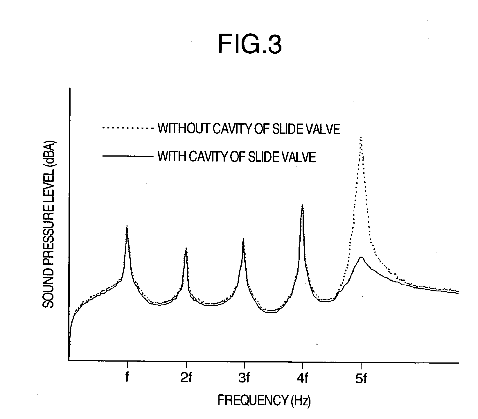
[0011] According to the present invention, in a two-stage screw compressor including a low pressure stage casing provided with a low pressure stage compression mechanism, a discharge casing provided on a discharge side of the low pressure stage casing, a high pressure stage casing provided with a high pressure stage compression mechanism, and intermediate stage casings for connecting the discharge casing and the high pressure stage casing, and accommodating an electric motor, a cavity is formed on a discharge casing side in the slide valve to enlarge the capacity of a discharge space formed in the discharge casing, and thereby internal resonance occurring in the discharge casing is prevented. Therefore, the internal resonance occurring in the discharge casing is prevented with a simple structure and significant noise reduction can be realized.

Problems solved by technology

However, if adopting the above described means, it is necessary to cover the entire cast casing with the noise absorbing material in the case of sticking the noise absorbing material on the casing, and thus it is often difficult in the case of a screw compressor having a complicated cast shape.
Further, in the case of the means according to the double structure of the casing and the rib addition, there are the problems of complication of the cast shape and increase in the cast weight.
In addition, any of the above described prior arts does not take account of increase in noise due to internal resonance in a discharge casing in a two-stage screw compressor, which includes a low pressure stage casing provided with a low pressure stage compression mechanism, the discharge casing provided on a discharge side of the low pressure stage casing, a high pressure stage casing provided with a high pressure stage compression mechanism, and an intermediate stage casing for connecting the discharge casing and the high pressure stage casing and accommodating an electric motor.

Method used


Image

  • Two-stage screw compressor
  • Two-stage screw compressor
  • Two-stage screw compressor

Examples


Embodiment Construction

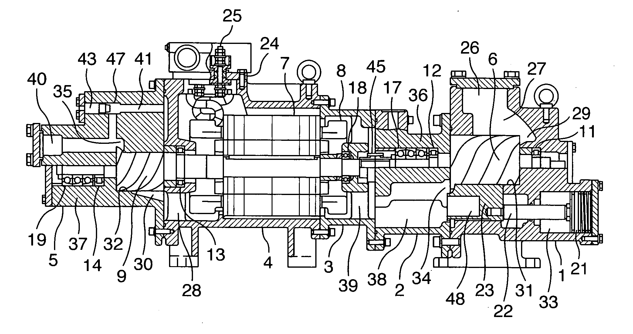
[0017]FIG. 1 shows one embodiment of a two-stage screw compressor of the present invention. The screw compressor includes a low pressure stage casing 1 having an inlet opening 26, a discharge casing 2 connected to a discharge side of the low pressure stage casing 1 and having a gas passage 38, a motor cover (intermediate stage casing) 3 which is connected to a downstream side of the discharge casing 2, has a gas passage 39, and accommodates a coil end 8 of an electric motor 7, a motor casing (intermediate stage casing) 4 accommodating the electric motor 7, and a high pressure stage casing 5 having a discharge port 40. These members are connected with bolts or the like to be integrated.

[0018] In the low pressure stage casing 1, there are formed a cylindrical bore 31, an inlet port 29 which introduces a refrigerant gas into the cylindrical bore 31, a piston chamber 33 which accommodates a piston 21 for driving a slide valve 23, and the like. In the cylindrical bore 31, a low pressure...


PUM


Abstract

A two-stage screw compressor of the invention includes a low pressure stage casing provided with a low pressure stage compression mechanism, a discharge casing provided on a discharge side of the low pressure stage casing, a high pressure stage casing provided with a high pressure stage compression mechanism, and intermediate stage casings for connecting the discharge casing and the high pressure stage casing, and accommodating an electric motor. In such a two-stage screw compressor, a cavity is formed on a discharge casing side in the slide valve so as to enlarge the capacity of a discharge space formed in the discharge casing. Thereby, internal resonance occurring in the discharge casing is prevented.

Description

INCORPORATION BY REFERENCE [0001] The present application claims priority from Japanese application JP 2005-190879 filed on Jun. 30, 2005, the content of which is hereby incorporated by reference into this application. BACKGROUND OF THE INVENTION [0002] The present invention relates to a two-stage screw compressor used for a screw refrigerator or the like. [0003] Regarding a noise spectrum generated by a screw compressor, it is known that a fundamental frequency obtained by multiplying the number of teeth of a male rotor by a rotational frequency, and a higher harmonic component of the fundamental frequency constitute a dominant peak. As means of reducing the noise, various measures such as sticking a noise absorbing material to a casing, enhancing sound insulation performance by forming a casing to have a double structure, or enhancing rigidity of a casing by adding a rib thereto have been taken. As a single-stage single screw compressor, there is the one in which a resonance space...

Claims


Application Information

Patent Timeline
Patent Type & Authority Applications(United States)
IPC IPC(8): F04B17/00
CPCF04C18/16F04C23/001F04C29/068F04C29/026F04C28/12
Inventor KATO, EISUKEHIOKI, YASUHIRONOZAWA, SHIGEKAZU
Owner HITACHI APPLIANCES INC
Learn More