Dry etching method
a technology of dry etching and etching plate, which is applied in the direction of decorative surface effects, electrical equipment, decorative arts, etc., can solve the problems of unstable plasma, difficult to suitably control the processing feature of the trench sidewall, and the pressure regulation valve cannot follow the gas
- Summary
- Abstract
- Description
- Claims
- Application Information
AI Technical Summary
Problems solved by technology
Method used
Image

Examples
first example
[0023] A dry etching method according to a first example of the invention is described with reference to FIGS. 1 to 4.
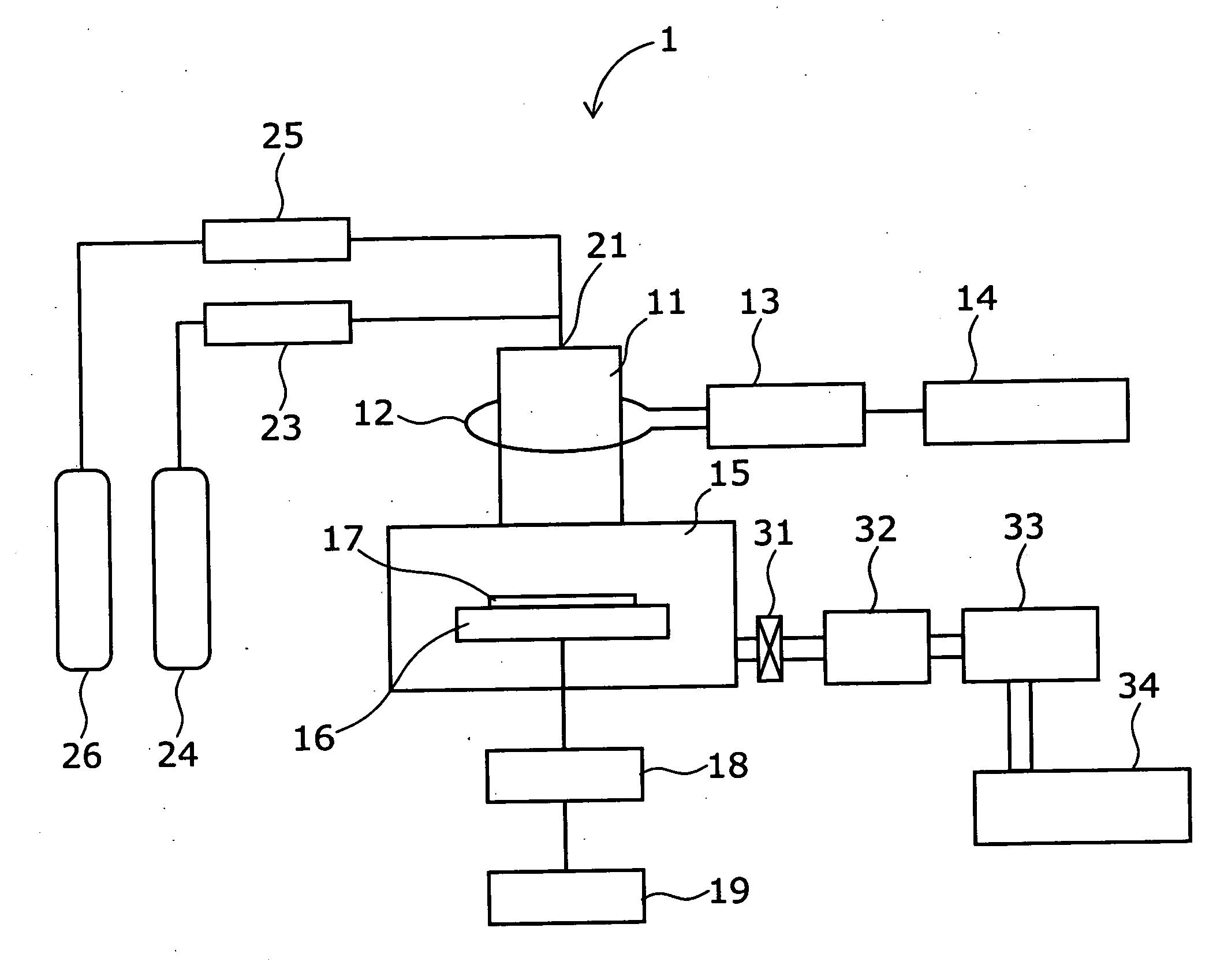
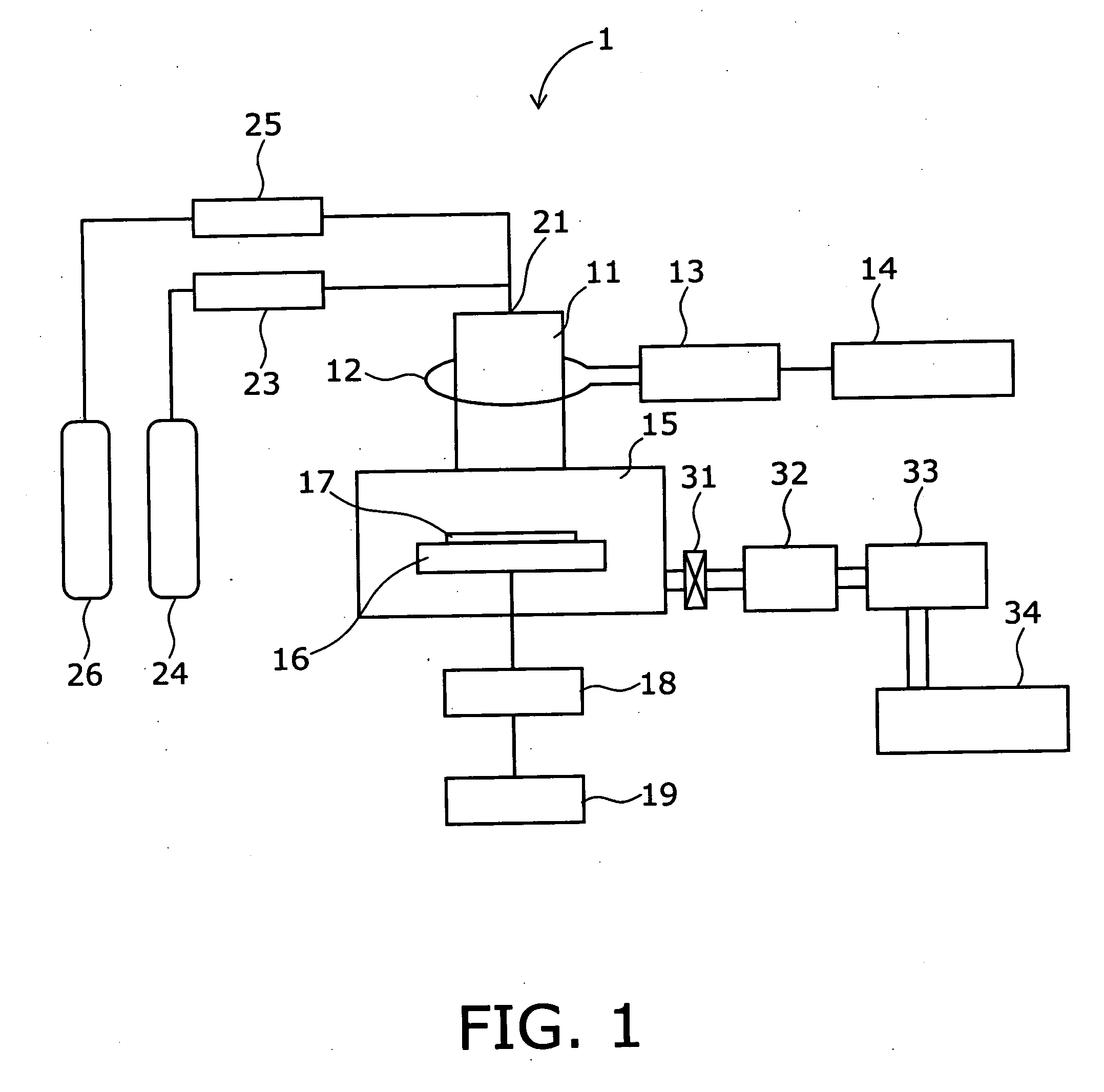
[0024]FIG. 1 is a configuration diagram that schematically shows a dry etching apparatus for use in dry etching a workpiece.
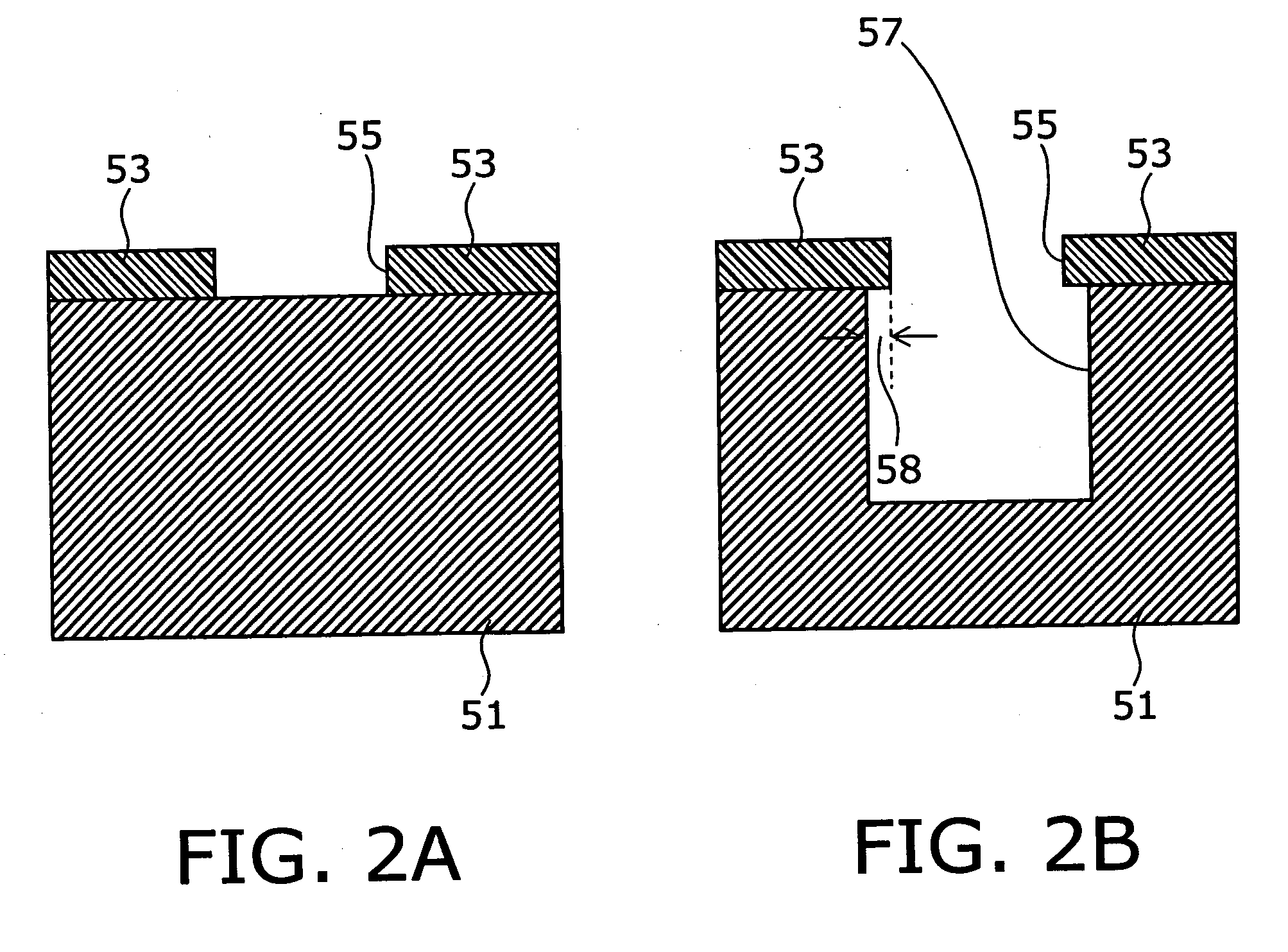
[0025]FIG. 2A is a schematic cross section of a Si substrate before dry etching, and FIG. 2B is a cross section that schematically shows the shape of a trench formed by the dry etching method and the resulting amount of undercut on the sidewall.
[0026]FIG. 3 shows the amount of undercut versus the depositive gas flow rate.
[0027]FIG. 4 shows the etching rate versus the etching gas flow rate.
[0028] As shown in FIG. 1, a dry etching apparatus 1, which illustratively has an inductively coupled plasma (ICP) source, comprises a plasma generating chamber 11 and a reaction chamber 15 connected to the plasma generating chamber 11. An antenna 12 for supplying radio-frequency energy to the plasma generating chamber 11 is installed on the periphery of t...
second example
[0044] A dry etching method according to a second example of the invention is described with reference to FIG. 7.
[0045]FIG. 7 shows the amount of undercut versus the depositive gas flow rate. This example is different from the first example in using C4F6 as a depositive gas. In the following, elements identical or corresponding to those in the first example are marked with like reference numerals and not described in detail, and different elements are described.
[0046] The dry etching apparatus used in this example has the same configuration as that of the first example except that the depositive gas 26 shown in FIG. 1 is C4F6 (hexafluorocyclobutene). The elements such as the radio-frequency power, the pressure in the reaction chamber 15, and the Si substrate 51 are the same as those of the first example.
[0047]FIG. 7 shows the amount of undercut 58 versus the C4F6 gas flow rate so as to be compared with C5F8 used in the first example and C4F8 used conventionally. The horizontal an...
third example
[0052] A dry etching method according to a third example of the invention is described with reference to FIGS. 9 and 10. FIG. 9 is a configuration diagram that schematically shows a dry etching apparatus for use in dry etching a Si substrate, and FIG. 10 shows the amount of undercut versus the flow rate of CO gas added as a depositive gas. This example is different from the first example in using C4F8 and additionally CO gas as depositive gases. In the following, elements identical or corresponding to those in the first example are marked with like reference numerals and not described in detail, and different elements are described.
[0053] As shown in FIG. 9, the dry etching apparatus 2 has a supply system for CO (carbon monoxide) gas 28 in addition to the dry etching apparatus 1 of the first example. The CO gas 28 stored in a cylinder is fed via a flow rate controller 27 into the gas inlet 21 on top of the plasma generating chamber 11. The depositive gas 26 stored in another cylind...
PUM
| Property | Measurement | Unit |
|---|---|---|
| Flow rate | aaaaa | aaaaa |
| Flow rate | aaaaa | aaaaa |
| Flow rate | aaaaa | aaaaa |
Abstract
Description
Claims
Application Information
 - R&D
- Intellectual Property
- Life Sciences
- Materials
- Tech Scout
- Unparalleled Data Quality
- Higher Quality Content
- 60% Fewer Hallucinations
Browse by: Latest US Patents, China's latest patents, Technical Efficacy Thesaurus, Application Domain, Technology Topic, Popular Technical Reports.
© 2025 PatSnap. All rights reserved.Legal|Privacy policy|Modern Slavery Act Transparency Statement|Sitemap|About US| Contact US: help@patsnap.com