
Bi-axial swivel assembly in electronic apparatus

a technology of electronic equipment and swivel assembly, which is applied in the field of electronic equipment, can solve the problems of frequent load on wires, large flexure on wires, etc., and achieve the effect of relieving the load on wires

Inactive Publication Date: 2006-12-28
FUJITSU LTD
View PDF13 Cites 19 Cited by
  • Summary
  • Abstract
  • Description
  • Claims
  • Application Information

AI Technical Summary

Benefits of technology

The present invention provides a bi-axial swivel assembly that can relieve a load applied to a wire. The assembly includes a pair of coaxial bearings, support shafts, a hollow space within one of the support shafts, a support member, a tube, a second hollow space within the tube, a bracket, a perpendicular surface, a restriction cam, and a recess. The bracket can rotate around the support shafts and the wire is protected from flexure. The assembly allows for the rotation of the bracket and support shafts around the longitudinal axis of the support shaft as long as the restriction cam is inside the imaginary reference plane. The wire can penetrate through the hollow spaces and is protected from larger flexure. The bi-axial swivel assembly can be incorporated into electronic apparatus such as cellular phones.

Problems solved by technology

The wire is also forced to suffer from a larger flexure every time the display enclosure rotates around the support shaft.
The wire in this manner suffer from a frequent load.

Method used


Image

  • Bi-axial swivel assembly in electronic apparatus
  • Bi-axial swivel assembly in electronic apparatus
  • Bi-axial swivel assembly in electronic apparatus

Examples


Embodiment Construction

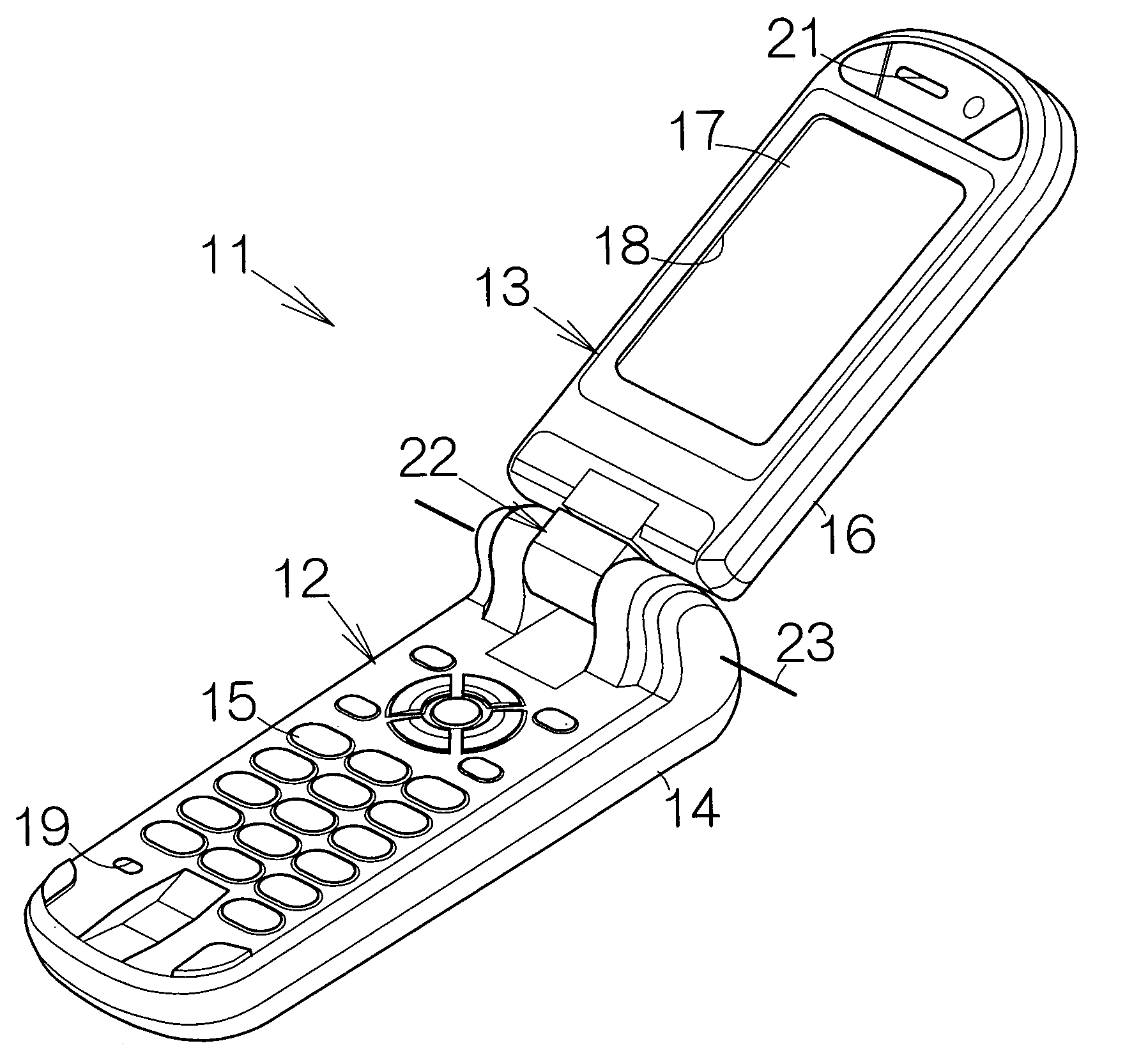
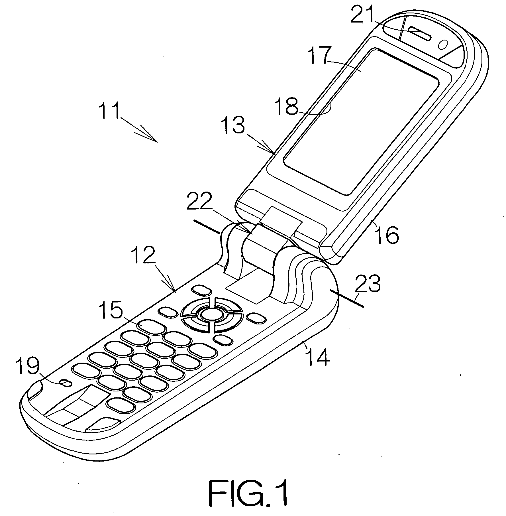
[0032]FIG. 1 schematically illustrates a cellular or mobile phone terminal 11 of a so-called flip or clamshell type as an example of an electronic apparatus. The cellular phone terminal 11 includes a transmitter 12 and a receiver 13. The transmitter 12 has a main enclosure 14 serving as a first enclosure according to the present invention. A printed circuit board, not shown, is incorporated within the main enclosure 14. Processing circuits, such as a central processing unit (CPU) and a memory, are mounted on the printed circuit board as conventionally known. Input keypads 15, such as an on-hook key, an off-hook key, ten keys, and the like, are embedded in the front flat surface of the transmitter 12. The CPU operates in response to the manipulation of the input keypads 15. The main enclosure 14 may be molded from a reinforced resin material, for example.

[0033] The receiver 13 has a display enclosure 16 serving as a second enclosure according to the present invention. A flat display...


PUM


Abstract

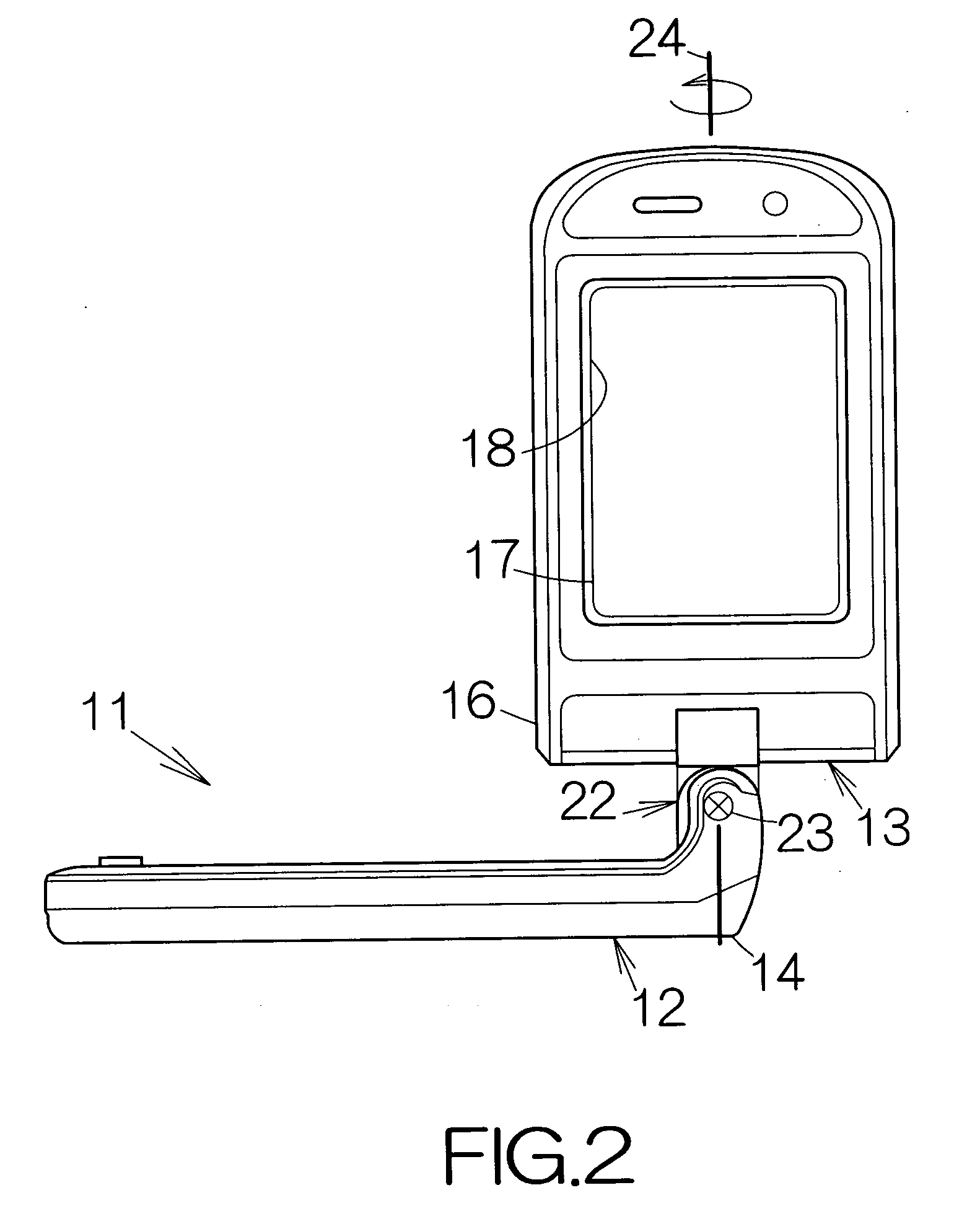
A bi-axial swivel assembly allows the rotation of a bracket around the longitudinal axis of a support shaft when the restriction cam lies inside an imaginary reference plane. The attitude of the bracket is allowed to change around the longitudinal axis of the support shaft. Only if the bracket allows the restriction cam get off a recess, the perpendicular surface serves to prevent the restriction cam from protruding outside the imaginary reference plane. The attitude of the bracket can be prevented from changing around the rotation axis perpendicular to the longitudinal axis. The bi-axial swivel assembly allows the wire to penetrate through first and second hollow spaces. When the bracket rotates around the longitudinal axis, the wire is only forced to suffer from a slight torsion within the first hollow space. The wire can be protected from a larger flexure.

Description

BACKGROUND OF THE INVENTION [0001] 1. Field of the Invention [0002] The present invention relates to an electronic apparatus such as a cellular or mobile phone terminal. In particular, the invention relates to a cellular phone terminal of a so-called flip or clamshell type. [0003] 2. Description of the Prior Art [0004] A cellular or mobile phone terminal of a so-called clamshell type, including a bi-axial swivel assembly, is well known as disclosed in Japanese Patent Application Publication 2005-023958. The cellular phone terminal includes a main enclosure and a display enclosure. The bi-axial swivel assembly includes a support shaft fixed to the main enclosure. A support member is supported on the support shaft for relative rotation. A bracket is coupled to the support member for relative rotation around the rotation axis perpendicular to an imaginary plane including the longitudinal axis of the support shaft. The display enclosure is coupled to the bracket. [0005] An annular groov...

Claims


Application Information

Patent Timeline
Patent Type & Authority Applications(United States)
IPC IPC(8): H04M1/00
CPCH04M1/0212H04B1/38H04M1/02
Inventor TAKAGI, HISAMITSU
Owner FUJITSU LTD
Learn More