
Circuit breaker panel

Inactive Publication Date: 2006-12-28
KELLY SEAN F
View PDF22 Cites 22 Cited by
  • Summary
  • Abstract
  • Description
  • Claims
  • Application Information

AI Technical Summary

Benefits of technology

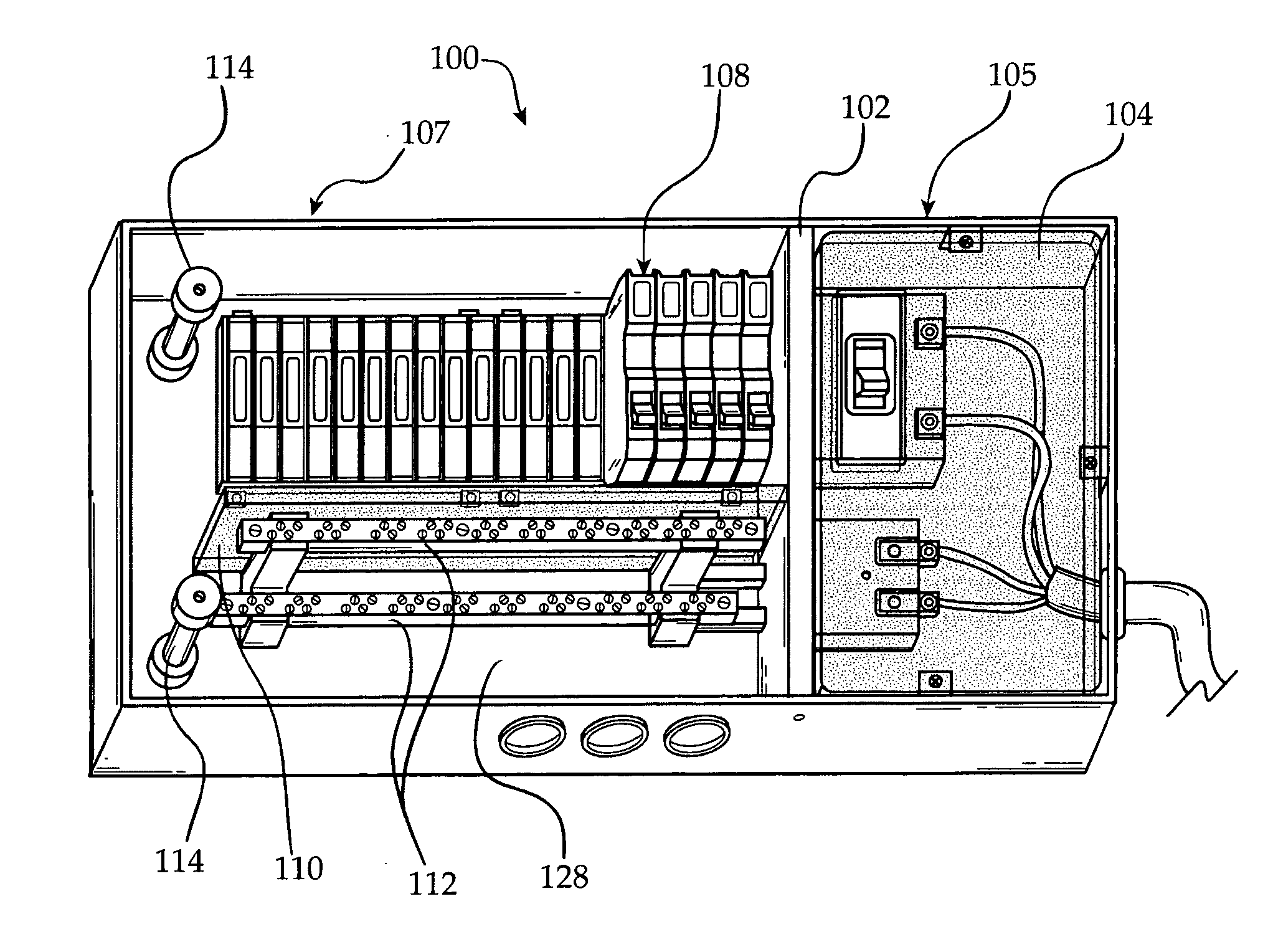
[0007] The present invention provides an improved breaker panel including safety shields, a unique bus bar configuration, and wiring bending posts. A safety shield over the main breaker covers the main lugs to thereby prevent a hand or a tool from contacting the main lugs. Thus the shield provides protection from electrocution for a person working on or near the breaker panel. Additional shields are provided, such as a shield separating the main breaker area from the circuit breaker area, and a shield separating the circuit breakers from the bus bars. The unique bus bar configuration of the present invention includes offset bus bars, such as by situating the neutral bus bar in a higher position than the ground bus bar. This configuration provides easier access to the ground or neutral bus and makes it easier to connect conductors to the ground bar or the neutral bar. Such offset thus reduces the chances that a person will connect more than the specified number of conductors to either the neutral or ground bus and reduces potential wire crowding. Such offset also reduces the chances that a person will connect a neutral conductor to a ground, or a ground conductor to neutral when the bus bars are meant to be unconnected. The breaker panel of the present invention also includes at least one bending post. The bending post allows for neat bending of wires within the breaker panel. The bending posts also prevent the wires from crossing over the circuit breakers and other components within the breaker panel.

Problems solved by technology

Such offset also reduces the chances that a person will connect a neutral conductor to a ground, or a ground conductor to neutral when the bus bars are meant to be unconnected.

Method used


Image

  • Circuit breaker panel
  • Circuit breaker panel
  • Circuit breaker panel

Examples


Embodiment Construction

[0016] Referring to FIGS. 1 and 1a, one embodiment of the improved breaker panel 100 of the present invention is shown. The breaker panel 100 includes a plurality of shields and partitions that protect against accidental or unintended contact with the live electrical wires contained within. The main breaker shield 104 covers the area occupied by the main breaker 116. The circuit breaker partition 102 divides the area within the breaker panel 100 into two distinct areas, more particularly the main breaker area 105 and the circuit breaker area 107. The main breaker area 105 is the area occupied by the main breaker 122 and the circuit breaker area 107 is the area occupied by the circuit breakers, and other items, such as the bus bars 112. The circuit breaker area 107 also includes a bus bar shield 110. The bus bar shield 110 serves to separate the bus bar 112 from the other items within the circuit breaker area 107, such as the circuit breakers 108 and any other devices.

[0017] In oper...


PUM


Abstract

The invention provides a circuit breaker panel with several safety features. The main breaker is separated from the circuit breakers by a non-conducting shield. The main breaker is also covered by a transparent, non-conducting shield. A further transparent non-conducting shield separates the circuit breakers from the neutral and ground bus bars. The neutral and ground bus bars are offset from one another to prevent wire crowding. Bending posts extending from the back plate of the panel help control the wire in the panel to prevent it from crossing bus bars or circuit breakers.

Description

CROSS-REFERENCE TO RELATED APPLICATIONS [0001] This application claims priority from U.S. Provisional Patent Application Ser. No. 60 / 677,729, filed May 4, 2005.FIELD OF THE INVENTION [0002] The present invention relates to a breaker panel, more particularly, to a breaker panel having a unique layout, including safety dividers and wire bending posts. BACKGROUND OF THE INVENTION [0003] Injury from electrical shock is possible whenever operating or working in close proximity to electrical equipment. When a person's body completes a circuit, connecting a power source with the ground, an electrical burn or injury occurs. Fatal injuries may result from high-voltage exposure. For this reason electrical safety is important in both work and home environments. While professionals that service or work in close proximity to live power lines are trained in proper handling procedures, many injuries and deaths occur each year. Furthermore, untrained individuals are often exposed live power lines a...

Claims


Application Information

Patent Timeline
IPC IPC(8): H02B1/20
CPCH02B1/42H02B1/14H02B1/202
Inventor KELLY, SEAN F.GAUS, JOHN P.
Owner KELLY SEAN F
Learn More