Manufacturing method of backlight unit, and backlight unit, electro-optic device, and electronic apparatus

a manufacturing method and technology of backlight units, applied in waveguide devices, lighting and heating devices, instruments, etc., can solve the problems of difficult manufacturing of large-sized display screens, the inability to secure the brightness of a display screen in a case of a large display screen, and the inability to manufacture large-sized display screens. , to achieve the effect of good optical characteristics, low brightness, and high lightness

Inactive Publication Date: 2006-12-28
SEIKO EPSON CORP
View PDF4 Cites 8 Cited by
  • Summary
  • Abstract
  • Description
  • Claims
  • Application Information

AI Technical Summary

Benefits of technology

[0009] An advantage of the invention is to provide a manufacturing method of a backlight unit in which the brightness uneveness can be lowered and the lightness is high, and to provide a backlight unit, electro-optic device, and electronic apparatus with good optical characteristics.
[0010] A backlight unit according to a first aspect of the invention includes a light source that irradiates light, and a diffusing plate that diffuses the light irradiated from the light source. The diffusing plate is provided with a first microlens of ellipsoid form, and a second microlens of ellipsoid form disposed in such a manner that long axes of the first microlens and the second microlens are approximately perpendicular to each other. A long axis direction of the first microlens and a long axis direction of the light source are arranged approximately parallel to each other. A long axis direction of the second microlens and the long axis direction of the light source are arranged approximately perpendicular to each other.
[0011] According to the first aspect of the invention, in a direct-lighting type backlight unit, in a case the long axis of the first microlens is arranged approximately parallel to a longitudinal direction of the light source, since the long axis of the microlens has smaller curvature than a short axis thereof, light is likely to diffuse and the brightness ununiformity can be lowered. In a case a short axis of the second microlens is arranged approximately parallel to the longitudinal direction of the light source, since the short axis of the microlens has larger curvature than the long axis thereof, light is likely not to diffuse and the lightness is heightened. Therefore, there can be provided the backlight unit in which the brightness ununiformity can be lowered and the lightness is high, by disposing the first microlens and the second microlens in such a direction that they are perpendicular to each other.
[0012] It is preferable that the backlight unit is a direct-lighting type.
[0013] In this case, the backlight unit is the direct-lighting type. Therefore, since a liner-shaped lamp is arranged between the reflecting plate and the diffusing plate, leakage of light can be reduced and there can be provided the backlight unit in which the brightness ununiformity can be more lowered and the lightness is high.
[0014] It is preferable that, in the backlight unit, the microlens is disposed in a zigzag fashion.

Problems solved by technology

In these methods, however, the number of the liner-shaped lamps capable of being mounted is limited.
Therefore, the brightness of a display screen cannot be secured in a case of a large display screen.
Moreover, it is difficult to manufacture a large-sized display screen due to a problem of mass of the light-guiding plate.
Therefore, there has been no problem in the brightness but may have been problem in a brightness ununiformity due to a brightness difference of the liner-shaped lamp itself and a brightness ununiformity between a portion directly under which the liner-shaped lamp exits and a portion directly under which no liner-shaped lamp exits.
In addition, if the liner-shaped lamp is spaced away from the face of the display screen surface, the brightness ununiformity is improved, but the brightness of the display screen is deteriorated, and thereby the thickness of the backlight unit is difficult to be reduced.
However, the increase in the number of the lamps may cause the problems such as the heat generation, cost, and others.

Method used


Image

  • Manufacturing method of backlight unit, and backlight unit, electro-optic device, and electronic apparatus
  • Manufacturing method of backlight unit, and backlight unit, electro-optic device, and electronic apparatus
  • Manufacturing method of backlight unit, and backlight unit, electro-optic device, and electronic apparatus

Examples


modified example 2

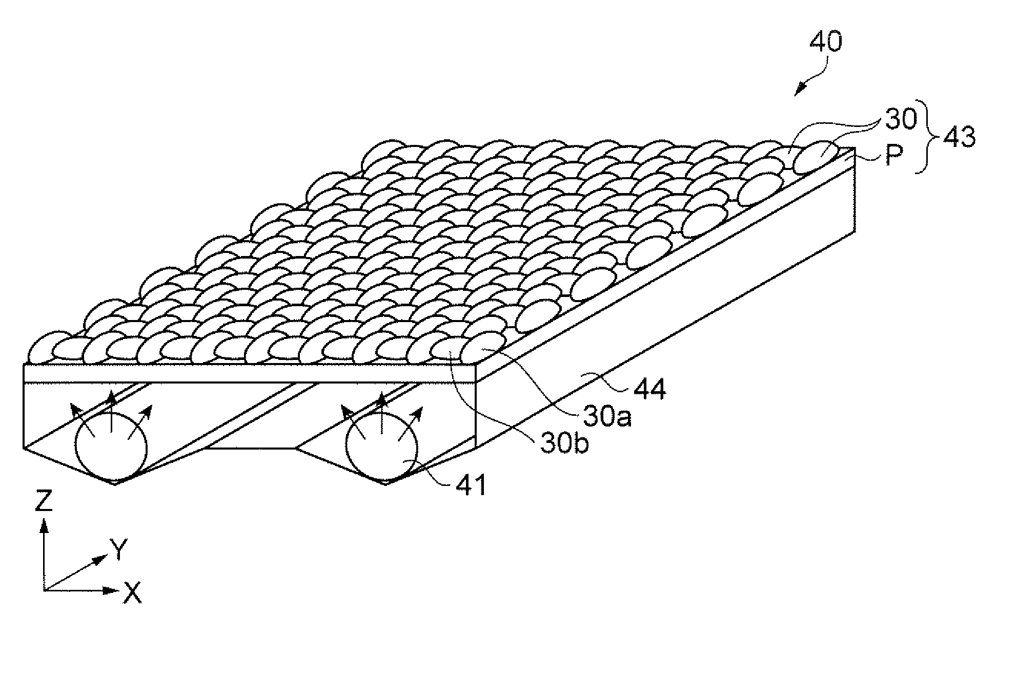
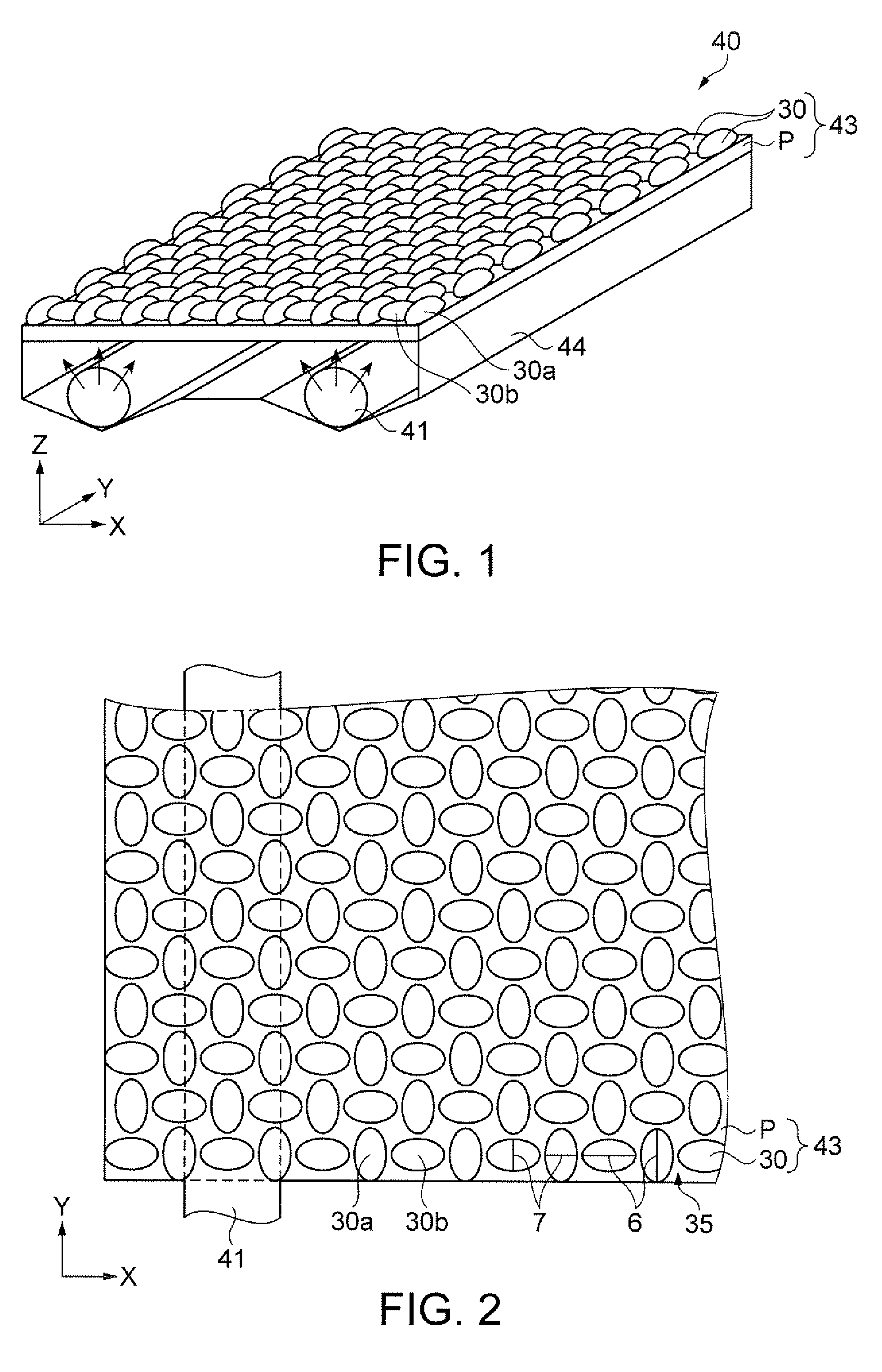
[0156] In the backlight unit 40 of the above-mentioned embodiment, the elliptical shaped microlens 30 is a convex shape, but not limited to this. For example, the elliptical shaped microlens 30 may be made in a concave shape by the pinning effect due to the coffee-stain phenomenon and the like. In this manner, also can be obtained the same effect as the above-mentioned embodiment, and there can be provided the backlight unit 40 in which the brightness ununiformity can be lowered and the lightness is high.

modified example 3

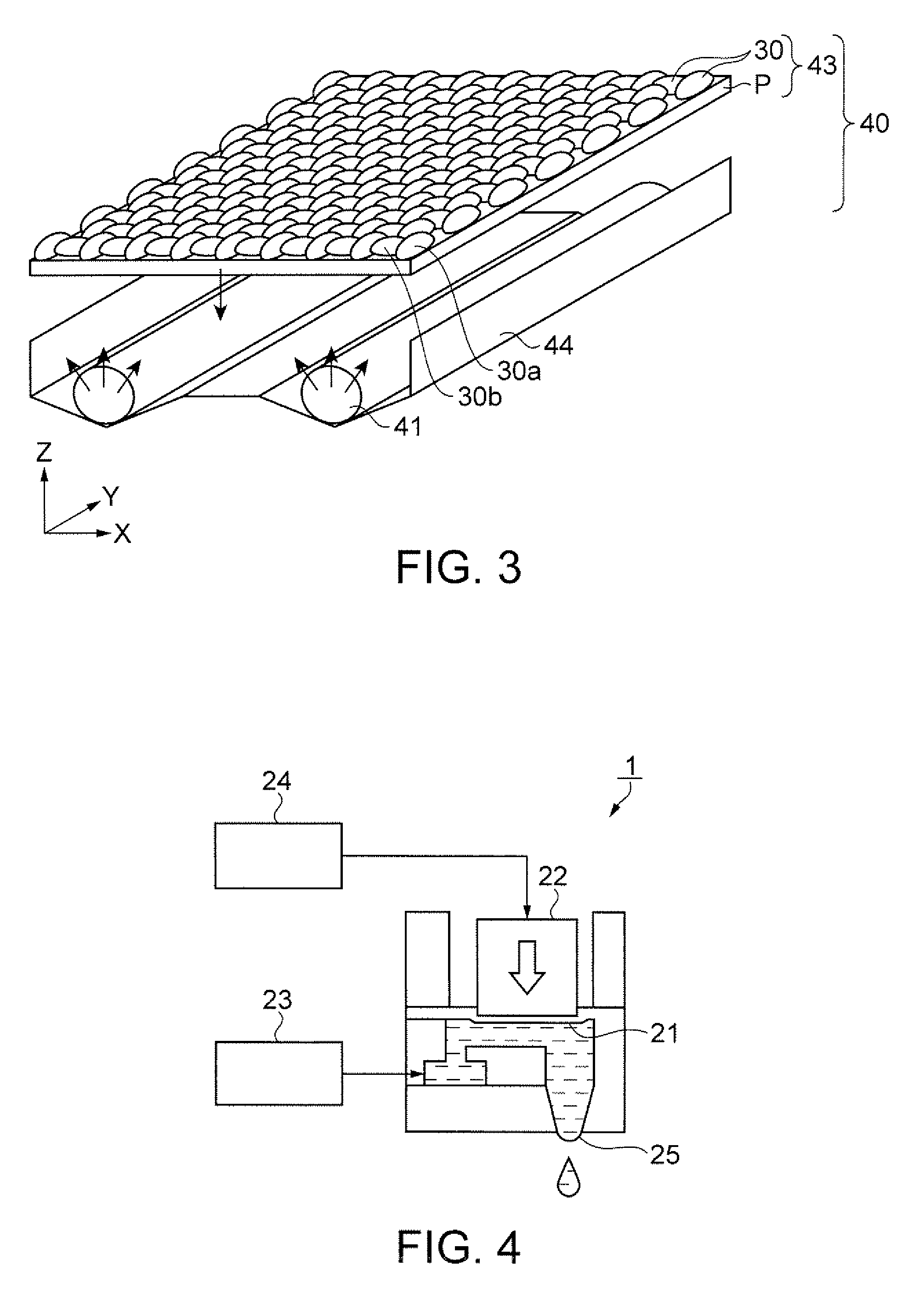
[0157] In the above-mentioned embodiment, the elliptical shaped microlens 30 is formed by the liquid droplet discharging method, but not limited to this. For example, the elliptical shaped microlens 30 may be made by use of molds and the like. In this manner, also can be obtained the same effect as the above-mentioned embodiment, and there can be provided the backlight unit 40 in which the brightness ununiformity can be lowered and the lightness is high.


PUM

PropertyMeasurementUnit
thicknessaaaaaaaaaa
thicknessaaaaaaaaaa
thicknessaaaaaaaaaa

Abstract

A backlight unit including: a light source that irradiates light; and a diffusing plate that diffuses the light irradiated from the light source, wherein the diffusing plate is provided with a first microlens of ellipsoid form, and a second microlens of ellipsoid form disposed in such a manner that long axes of the first microlens and the second microlens are approximately perpendicular to each other, and a long axis direction of the first microlens and a long axis direction of the light source are arranged approximately parallel to each other, and a long axis direction of the second microlens and the long axis direction of the light source are arranged approximately perpendicular to each other.

Description

BACKGROUND [0001] 1. Technical Field [0002] The present invention relates to a manufacturing method of a backlight unit, and to a backlight unit, an electro-optic device, and an electronic apparatus. [0003] 2. Related Art [0004] Conventionally, in a liquid crystal display device as an electro-optic device, there has been a light collecting method in which an optical sheet having a plurality of elliptical shaped microlenses is arranged in a backlight unit for liquid crystal display built in the liquid crystal display device so that light from a light source for illumination of the backlight unit is collected effectively to a liquid crystal element (pixel). Moreover, there has been reported many methods of forming a microlens by use of a droplet discharging method (for example, a first example of related art). [0005] As disclosed in a second example of related art, for example, there has been a backlight unit of an edge-lighting type (side-lighting type) which is constructed such that...

Claims


Application Information

Patent Timeline
Patent Type & Authority Applications(United States)
IPC IPC(8): G02F1/1335
CPCG02F1/133606G02F1/133604G02F1/13G02F1/1335
Inventor HASEI, HIRONORIINAGAKI, AKIRAARUGA, KAZUMI
Owner SEIKO EPSON CORP
Why Eureka
Try Eureka