
Video signal processing circuit, video signal display apparatus, and video signal recording apparatus

a video signal and display apparatus technology, applied in the direction of color burst signal generation/insertion, pulse automatic control, color television details, etc., can solve the problems of reducing accuracy, dot crawling and other picture quality problems, and achieve excellent two- or three-dimensional y/c separation and degradation of picture quality after y/c separation

Active Publication Date: 2006-12-28
MITSUBISHI ELECTRIC CORP
View PDF5 Cites 12 Cited by
  • Summary
  • Abstract
  • Description
  • Claims
  • Application Information

AI Technical Summary

Benefits of technology

[0018] The present invention addresses the problems described above, with an object of providing video signal processing circuits, video signal display devices, and video signal recording devices that can perform excellent two-dimensional or three-dimensional Y / C separation regardless of the line-to-line or frame-to-frame phase relationship of the composite video signal and regardless of the use of non-standard signals, and can prevent picture quality degradation after Y / C separation. Means of Solution of the Problems
[0025] According to the present invention, line-to-line or frame-to-frame differences in the color subcarrier phase are corrected to align the color subcarrier phase with sampling points having the phase relationship used in two-dimensional or three-dimensional Y / C separation, whereby excellent two- or three-dimensional Y / C separation can be obtained from signals in a plurality of television broadcast systems, regardless of the line-to-line or frame-to-frame phase relationship, or regardless of the use of non-standard signals, producing the effect that degradation of picture quality after Y / C separation can be prevented.

Problems solved by technology

The reduced accuracy results in dot crawl and other picture quality problems.

Method used


Image

  • Video signal processing circuit, video signal display apparatus, and video signal recording apparatus
  • Video signal processing circuit, video signal display apparatus, and video signal recording apparatus
  • Video signal processing circuit, video signal display apparatus, and video signal recording apparatus

Examples


first embodiment

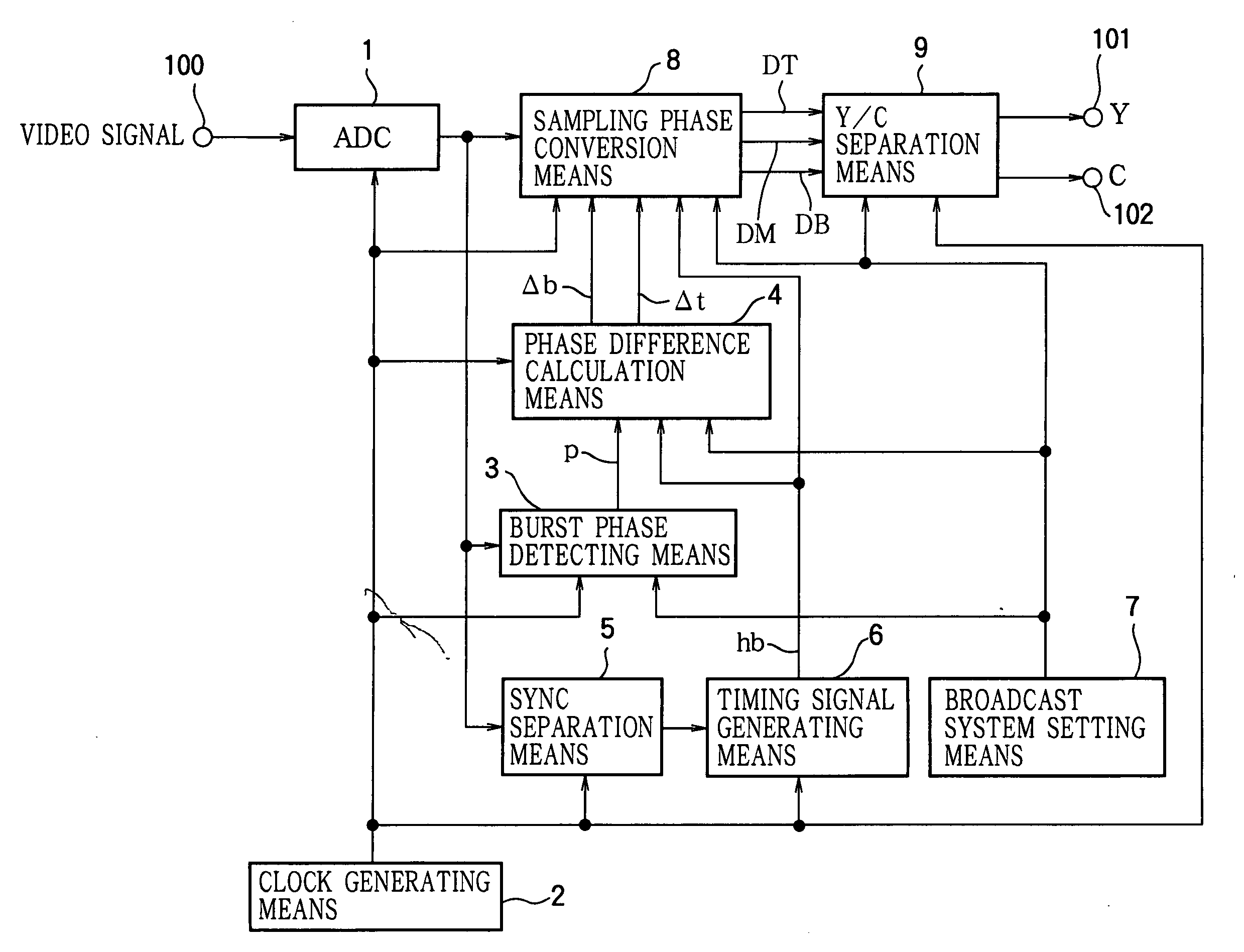
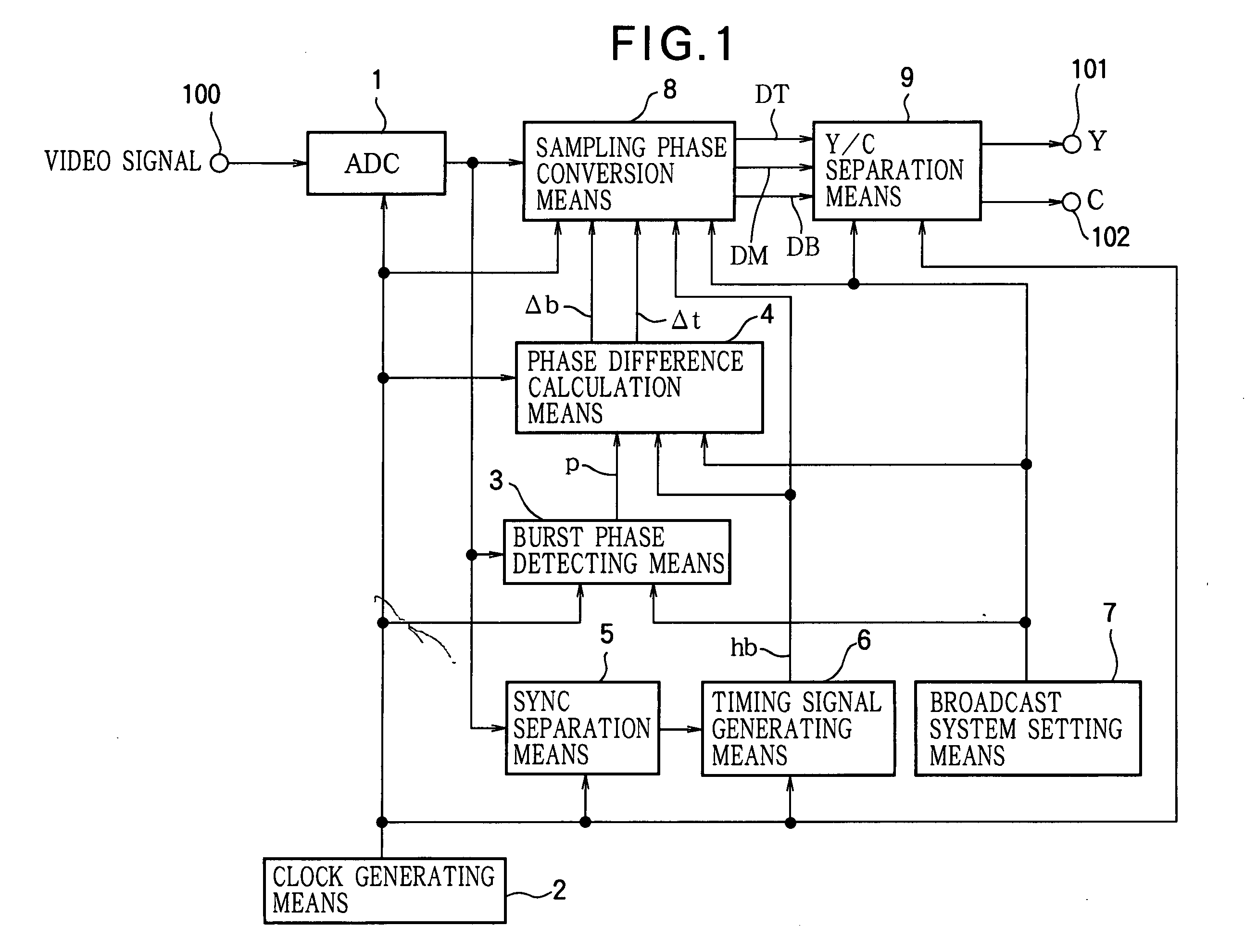
[0066]FIG. 1 is a block diagram showing an example of the structure of a video signal processing circuit according to a first embodiment of the invention. The video signal processing circuit in FIG. 1 comprises an A / D conversion means (analog-to-digital converter or ADC) 1, a clock generating means 2, a burst phase detecting means 3, a phase difference calculation means 4, a sync separation means 5, a timing signal generating means 6, a broadcast system setting means 7, a sampling phase conversion means 8, a Y / C separation means 9, an input terminal 100, and a pair of output terminals 101, 102.

Clock Generating Means 2

[0067] The clock generating means 2 generates a clock with a prescribed frequency X and supplies it to the A / D conversion means 1, burst phase detecting means 3, phase difference calculation means 4, sync separation means 5, timing signal generating means 6, sampling phase conversion means 8, and Y / C separation means 9.

[0068] The clock with frequency X generated by th...

second embodiment

[0167] In the first embodiment described above, the line-to-line phase error was obtained from consideration of the line-to-line phase inversion of π. In a second embodiment, described below, a correction is obtained by comparing phase information for a certain line with a fixed phase value.

[0168]FIG. 11 is a block diagram showing an example of the structure of a video signal processing circuit according to the second embodiment of the invention. Elements identical to elements shown FIG. 1 are denoted by the same reference numerals. As shown in FIG. 11, the video signal processing circuit of the second embodiment comprises an A / D conversion means 1, a clock generating means 2, a burst phase detecting means 3, a sync separation means 5, a timing signal generating means 6a, a broadcast system setting means 7, a Y / C separation means 9, a phase difference calculation means 60, a sampling phase conversion means 61,.an input terminal 100, and output terminals 101, 102.

[0169] The video s...

third embodiment

[0219] In the first and second embodiments described above, the phase of the video signal was corrected by the phase correction output from the phase difference calculation means. In a third embodiment, described below, the phase of the sampling clock is corrected by the phase correction output from the phase difference calculation means, thereby providing the video signal with the phase relationship used in Y / C separation.

[0220]FIG. 14 is a block diagram showing an example of the structure of a video signal processing circuit according to the third embodiment of the invention, denoting elements identical to elements shown in FIG. 1 or 11 by the same reference numerals. As shown in FIG. 14, the video signal processing circuit of the third embodiment comprises an A / D conversion means 1, a clock generating means 2, a burst phase detecting means 3, a sync separation means 5, a timing signal generating means 6b, a broadcast system setting means 7, a Y / C separation means 9, a clock phas...


PUM


Abstract

A video signal processing circuit that uses a prescribed clock signal to process a digitized composite video signal. A clock generating means (2) generates the prescribed clock signal; a burst phase detecting means (3) detects color subcarrier phase information (p) in each line of the composite video signal; a phase difference calculation means (4) finds the phase difference between phase information (p) from the burst phase detecting means and a prescribed reference phase; a sampling phase conversion means (8) corrects the sampling phase of the composite video signal according to phase corrections (Δb, Δt) obtained from the phase difference calculation means (4); a Y / C separation means (9) separates the luminance and chrominance signals from the composite video signal output from the sampling phase conversion means (8). Excellent two- or three-dimensional Y / C separation can be obtained regardless of the television broadcast system, even from a non-standard signal.

Description

FIELD OF THE INVENTION [0001] The present invention relates to the processing of a received composite video signal to separate the luminance and chrominance signals (Y / C separation), more particularly to video signal processing that converts the sampling phase of the composite video signal. BACKGROUND ART [0002] There are various standard analog color television (TV) broadcast systems, including the National Television System Committee (NTSC) system used in the United States and Japan, the Phase Alternation by Line (PAL) system used mainly in western Europe, and the Sequential Coleur avec Memoire (SECAM) system used in France and elsewhere. Due to the spread of video tape recorders (VTRs) and video games, non-standard video signals other than the signals (standard signals) used in the above standard television broadcast systems can also be found. In recent years, video signal processing devices that perform digital signal processing of standard and non-standard video signals used in...

Claims


Application Information

Patent Timeline
IPC IPC(8): H04N9/77H04N9/78
CPCH04N9/78
Inventor ASAMURA, MASAKOSUZUKI, YOSHITOGAI, TOSHIHIROMINAMI, KOJIYAMAKAWA, MASAKI
Owner MITSUBISHI ELECTRIC CORP
Learn More