
Multi-mode convection oven with flow control baffles

Inactive Publication Date: 2006-12-28
VIKING RANGE
View PDF15 Cites 63 Cited by
  • Summary
  • Abstract
  • Description
  • Claims
  • Application Information

AI Technical Summary

Benefits of technology

[0010] The combination of the large fan blade and baffle design allows the selected mode of oven operation to cook food accurately and evenly due, in part, to a more evenly distributed airflow and fewer hot spots and stagnant zones within the oven cavity.

Problems solved by technology

Further, a time delay can be included between either switching the fan from the first operating mode to the second operating mode or switching the fan from the second operating mode to the first operating mode.

Method used


Image

  • Multi-mode convection oven with flow control baffles
  • Multi-mode convection oven with flow control baffles
  • Multi-mode convection oven with flow control baffles

Examples


Embodiment Construction

[0028] Referring now in more detail to the drawing figures, wherein like reference numerals refer, where appropriate, to like parts throughout the several views, the figures illustrate an oven that embodies principles of the invention in preferred forms.

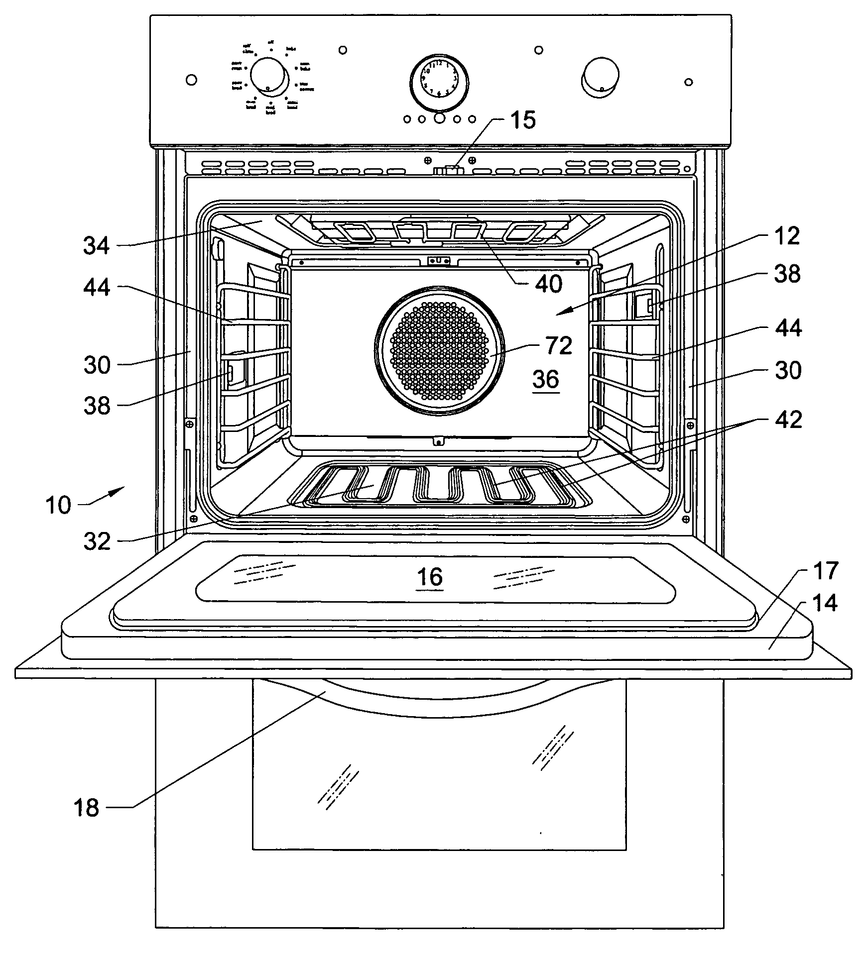
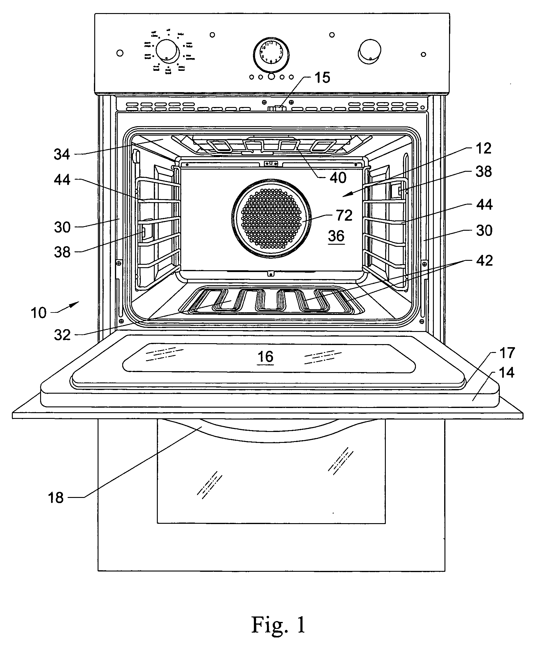
[0029]FIG. 1 shows a front view of an oven 10 that includes an oven cavity 12 and a door 14. The door 14 can include a seal 17, which assists in sealing the space between the door and the cavity when the door 14 is in a closed position. The door 14 is hingeable, generally within a range of at least 90°, to operate from a closed to an open position or an open to closed position. As shown in FIG. 1, when the door 14 is in an open position, the oven is capable of receiving items, such as food or other substances to be heated, in the cavity 12.

[0030] The door 14 can include any number of conventional features, such as a window 16 and a handle 18 as shown in FIG. 1. The door 14 generally includes a glass pack and other features that ins...


PUM


Abstract

An airflow control system for an oven having an oven cavity and a fan having a first operating mode for generating a first flow of air and a second operating mode for generating a second flow of air is provided. A baffle is included adjacent the fan to direct the first flow of air to a first region of the cavity in the first operating mode and to direct the second flow of air to a second region of the cavity in the second operating mode. A method of controlling airflow in an oven having an oven cavity is also detailed. The method can include different modes of operation, with different clockwise and counterclockwise rotational times for the fan, with different heating elements energized, or a combination of both, depending upon the food to be cooked in the oven.

Description

CROSS-REFERENCE TO RELATED APPLICATIONS [0001] This application claims the benefit of U.S. Provisional Application 60 / 678,317, filed May 6, 2005, incorporated by reference herein in its entirety.FIELD OF THE INVENTION [0002] This invention relates generally to cooking appliances, and more specifically to convection ovens. BACKGROUND OF THE INVENTION [0003] Ovens have long been used for cooking. Several types of conventional ovens exist. One is a convection oven, which features a fan designed to circulate air within the oven cavity creating convection currents. The fan also circulates the air past a heating element that heats the air to cooking temperatures; typically several hundred degrees. The hot circulating air currents pass over and around food in the oven cavity to facilitate cooking. Convection oven cooking is considered by many to be superior to standard radiant oven cooking. [0004] Conventional convection ovens suffer from a number of drawbacks. For example, some convention...

Claims


Application Information

Patent Timeline
IPC IPC(8): A21B1/22A21B1/00F27D11/00
CPCF24C15/325
Inventor CARBONE, PHILIP C.BREKKEN, MATTHEW E.PESCATORE, PETER F.MARTIN, DAVID M.BORAL, ANINDYA
Owner VIKING RANGE
Learn More