
Image forming apparatus

a technology of image formation and forming surface, which is applied in the field of image formation apparatus, can solve the problems of difficult and complicated determination of whether a positive or a negative correction value should be inputted with respect to the reference surface, and achieves the effect of easy and reliable adjustment of the image formation area

Inactive Publication Date: 2006-12-21
KONICA MINOLTA BUSINESS TECH INC
View PDF5 Cites 12 Cited by
  • Summary
  • Abstract
  • Description
  • Claims
  • Application Information

AI Technical Summary

Benefits of technology

[0010] The object of the present invention is to find out a method for easy and reliable adjustment of the image formation area on the front and back surfaces in an image forming apparatus for image formation on both surfaces.

Problems solved by technology

Thus, even if the user compares the test charts and measures the difference, the adjustment of the image formation area will become difficult if the surface serving as a reference cannot be identified.
Thus, when the correction value is inputted, it is complicated to determine whether a positive correction value or a negative correction value should be inputted with respect to the reference surface.

Method used


Image

  • Image forming apparatus
  • Image forming apparatus
  • Image forming apparatus

Examples


Embodiment Construction

[0031] Referring to the drawings, the following describes the best forms of embodiments of the image forming apparatus according to the present invention.

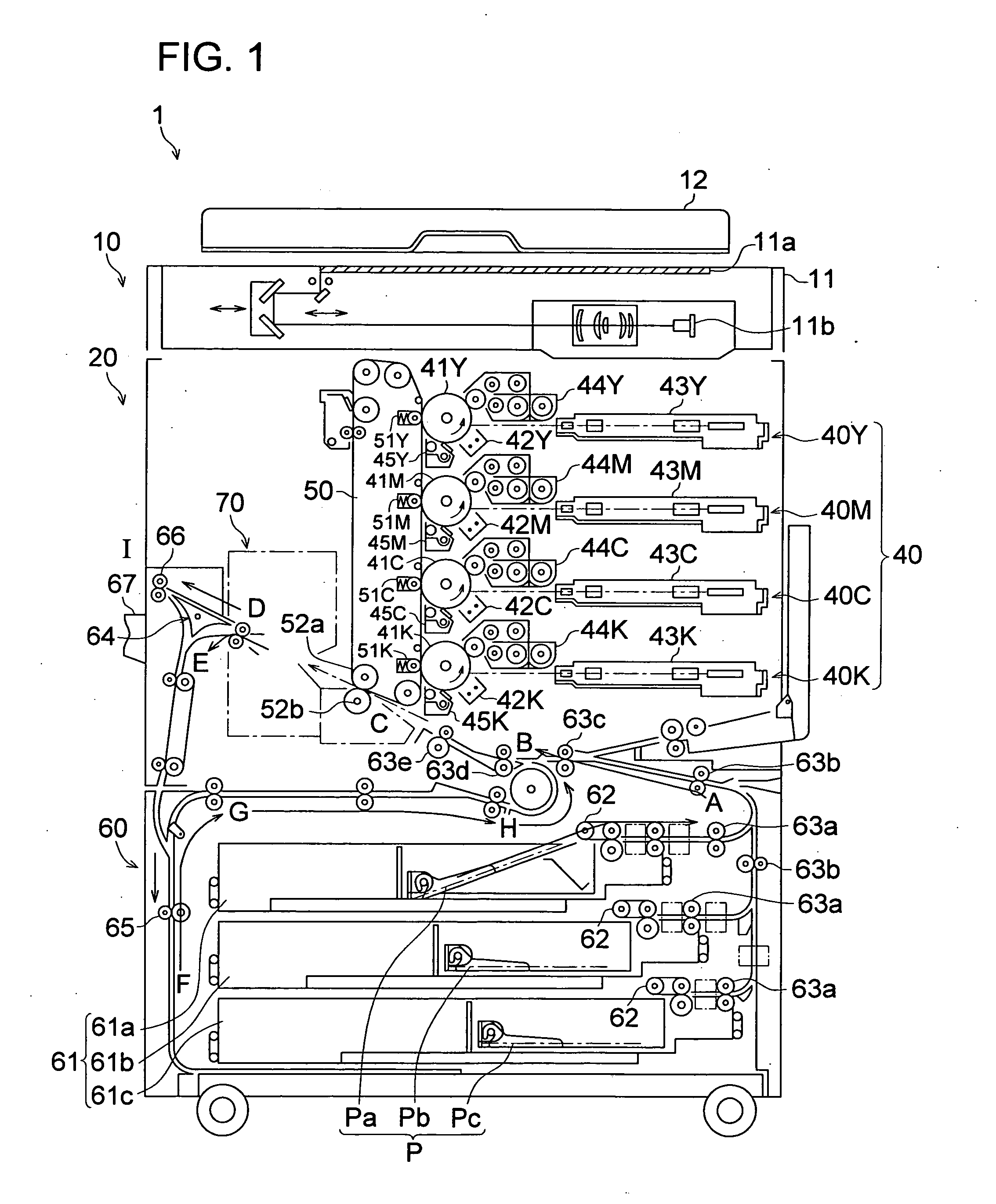
[0032]FIG. 1 is a diagram representing the overall arrangement of the image forming apparatus 1. The image forming apparatus 1 is made of an image reading section 10 and image forming apparatus main body 20. The image reading section 10 is arranged on the upper portion of the image forming apparatus main body 20.

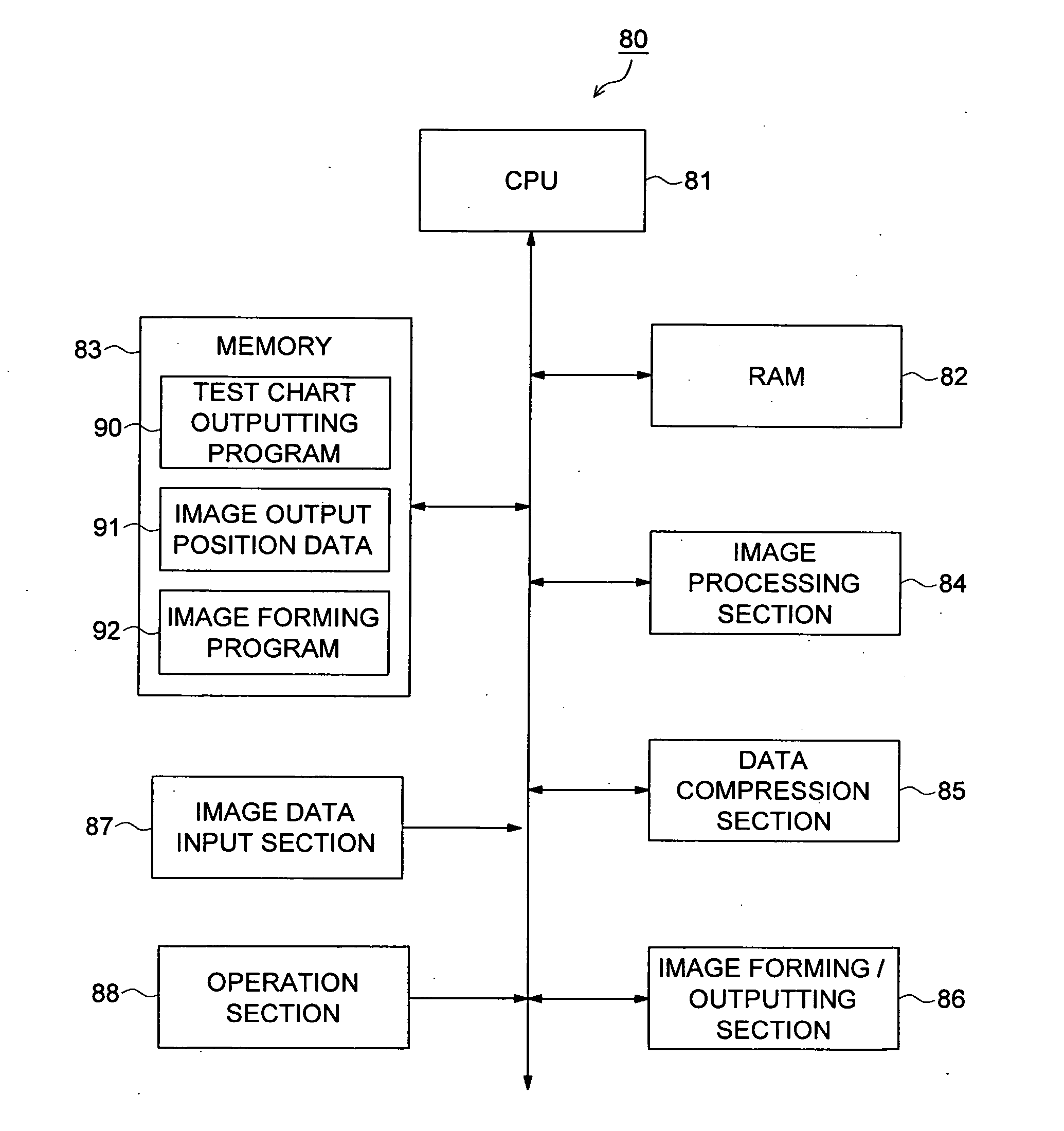
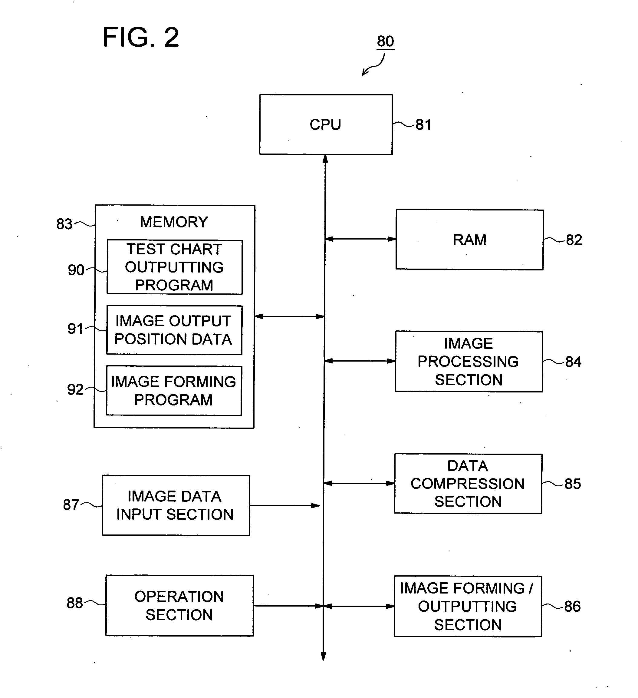
[0033] The scanner 11 reads the image of the document placed between the platen glass 11a and scanner cover 12. Light is projected on the document and the reflected light is captured by the CCD (Charge Coupled Device) 11b. Electronic data is generated by photoelectric conversion from the light having been captured, and is outputted RGB-based image data to the control circuit 80 to be described later.

[0034] The image forming apparatus main body 20 is made up of an image forming section 40, intermediate transfer belt 50, p...


PUM


Abstract

An image forming apparatus including: an image forming section for forming images on both surfaces of a recording medium; and a control section for controlling the image forming section to form, on each surface of the recording medium, a first image and image each including a test chart image for detecting a deviation between image formation areas on both surfaces of the recording medium; wherein at least one of the image and the second image includes an identification image for identifying a reference surface and the other surface the recording medium.

Description

CROSS REFERENCE TO RELATED APPLICATION [0001] The present application is based on Japanese Patent Application No. 2005-177691 filed with Japan Patent Office on Jun. 17, 2005. BACKGROUND OF THE INVENTION [0002] 1. Field of the Invention [0003] The present invention relates to an image forming apparatus, particularly to an image forming apparatus wherein a visible identifier is attached to the test chart for adjusting the area for image formation at the time of double-sided printing, thereby facilitating the user's adjustment work. [0004] 2. Description of Related Art [0005] In the image-forming apparatus such as a copying machine, printer and facsimile, a technique for adjusting the area for image formation on a substrate has been known. [0006] As an example of the technique for adjusting the image formation areas on the front and back in double-sided printing, Unexamined Japanese Patent Application Publication No. 2004-25784 discloses an image forming apparatus, wherein the pattern ...

Claims


Application Information

Patent Timeline
Patent Type & Authority Applications(United States)
IPC IPC(8): G06K15/00
CPCB41J29/393B41J3/60
Inventor HONMA, MIKIMASA
Owner KONICA MINOLTA BUSINESS TECH INC
Learn More