
Projector and focus adjustment method

a technology of projector and focus adjustment, applied in the field of projector, can solve the problems of annoying some operators, unnecessary focus adjustment, and operation for readjusting the focus, and achieve the effect of reading the focus in a short tim

Inactive Publication Date: 2006-12-21
NEC DISPLAY SOLUTIONS LTD
View PDF5 Cites 41 Cited by
  • Summary
  • Abstract
  • Description
  • Claims
  • Application Information

AI Technical Summary

Benefits of technology

[0010] Accordingly, it is an object of the present invention to solve the above-mentioned problems and to provide a projector that can readjust the focus in a short time.
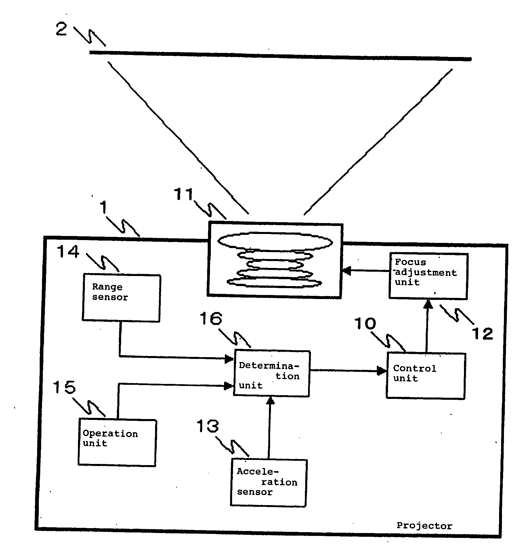
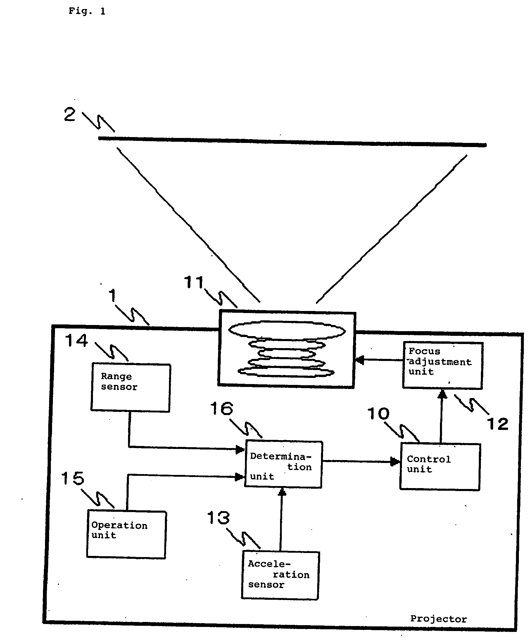
[0017] With the above-mentioned arrangement, for example, when the projector is moved in the direction approaching the screen after the autofocus process is performed, the determination unit detects the movement of the projector (housing) and determines the direction and the distance that the projector (housing) has moved. Then, the control unit determines the direction and the distance that the focus lens is to be moved in accordance with the determined direction and the determined distance of the projector (housing) and moves the focus lens in accordance with the determined direction and the determined distance of the focus lens. In this way, by moving the focus lens with prediction control, the position of the focus lens, after the projector has been moved, is closer to the position of focus lens in which the projected image is in focus than to the position of the focus lens before the projector was moved. Accordingly, the time required for the autofocus process after moving the projector can be shortened.
[0018] According to the present invention, because the focus lens starts to move, based on prediction control, while the projector starts to move, it is possible to shorten the time that is needed for the autofocus process to operate after the projector has moved. Therefore, the focus can be adjusted at higher speed than the projector disclosed in Japanese Patent Laid-Open No. 2003-131118.

Problems solved by technology

The operation for readjusting the focus, as described above, is annoying for some operators.
However, there are following problems in the projector disclosed in Japanese Patent Laid-Open No. 2003-131118.
However, the amount of time that is required from starting the autofocus function until focus is achieved is basically equal to the amount of time that it takes the user to push the bottom to start the autofocus function, and improvement have not yet been introduced from the standpoint of being able to readjust the focus in a short time.
However, when infrared rays radiated from a range sensor on the projector side (a sensor for measuring a projection distance [a distance from a projection lens to the screen]) are cut off by someone or something, unnecessary focus adjustment is performed.

Method used


Image

  • Projector and focus adjustment method
  • Projector and focus adjustment method
  • Projector and focus adjustment method

Examples


first embodiment

[0030]FIG. 1 is a block diagram showing a configuration of a projector according to the first embodiment of the present invention. Referring to FIG. 1, projector 1 according to the first embodiment is a transportable projector and includes control unit 10, lens unit 11, focus adjustment unit 12, acceleration sensor 13, range sensor 14, operation unit 15, and determination unit 16. In addition, projector 1 also includes the existing elements for carrying out functions as a projector, such as a light source, a display device that reflects or transmits beams from the light source and that is typified by a liquid crystal device, an image processing unit for applying image processes (such as A / D conversion, synchronization signal separation, rewriting and reading data to / from a frame memory) to video signals from the outside, and a driving unit for driving the display device in accordance with image data from the image processing unit, not shown. Since these existing elements are well kn...

second embodiment

[0056] In the configuration shown in FIG. 1, when projector 1 is arranged such that the optical axis of projection lens 11 is vertical to the surface of screen 2, a rectangular image in which the top-and-bottom and right-and-left of the projection screen are even is projected on screen 2. On the other hand, when projector 1 is arranged such that the optical axis of projection lens 11 tilts relative to the surface of screen 2, a keystone distortion is generated in the image projected on screen 2. In the second embodiment, explanations are given of an example in which a function for correcting the keystone distortion (keystone distortion correction process) together with the autofocus process is added to the projector according to the first embodiment, as described above.

[0057]FIG. 7 is a block diagram showing a configuration of a projector according to the second embodiment of the present invention. In FIG. 7, the same reference numerals are applied to the same elements as in FIG. 1...


PUM


Abstract

A transportable projector includes a focus adjustment unit for moving a focus lens in a projection lens, an acceleration sensor for detecting acceleration in a direction along an optical axis of the projection lens in the projector, a determination unit for determining whether the projector is in a stationary state or in a moving state in accordance with an output of the acceleration sensor and for respectively determining the direction to which the projector has moved and the distance that the projector has moved in accordance with an output of the acceleration sensor, and a control unit for controlling movement of the focus lens by the focus adjustment unit in accordance with the determined direction and the determined distance of the projector.

Description

BACKGROUND OF THE INVENTION [0001] 1. Field of the Invention [0002] The present invention relates to a projector having an autofocus function. [0003] 2. Description of the Related Art [0004] There is provided a projector having an autofocus function. In such a projector, usually, at startup or at the time of pushing a specific button, the autofocus function operates to stop a focus lens at a position where an image projected on a screen is in focus. An operator can set up the projector easily in a short time by using this autofocus function. [0005] However, in setting up the projector, there is a case in that, after the focus is adjusted, the projector main body is moved toward or away from the screen to adjust the size or the like of the projected image. In this case, the operator again adjusts again the focus with the autofocus function by pushing the specific button or the like after the projector main body has been moved. [0006] The operation for readjusting the focus, as descri...

Claims


Application Information

Patent Timeline
IPC IPC(8): G03B3/00
CPCG03B21/53H04N9/3197H04N9/3185H04N9/317
Inventor HIGASHI, HIDEAKI
Owner NEC DISPLAY SOLUTIONS LTD
Learn More