
Method and apparatus to control a temperature of a printer head chip

a printer head chip and temperature control technology, applied in the field of imageforming apparatus, can solve the problems of printing abnormalities, ink droplets being ejected too early, and printer head chips tending to overhea

Inactive Publication Date: 2006-12-21
SAMSUNG ELECTRONICS CO LTD
View PDF2 Cites 33 Cited by
  • Summary
  • Abstract
  • Description
  • Claims
  • Application Information

AI Technical Summary

Benefits of technology

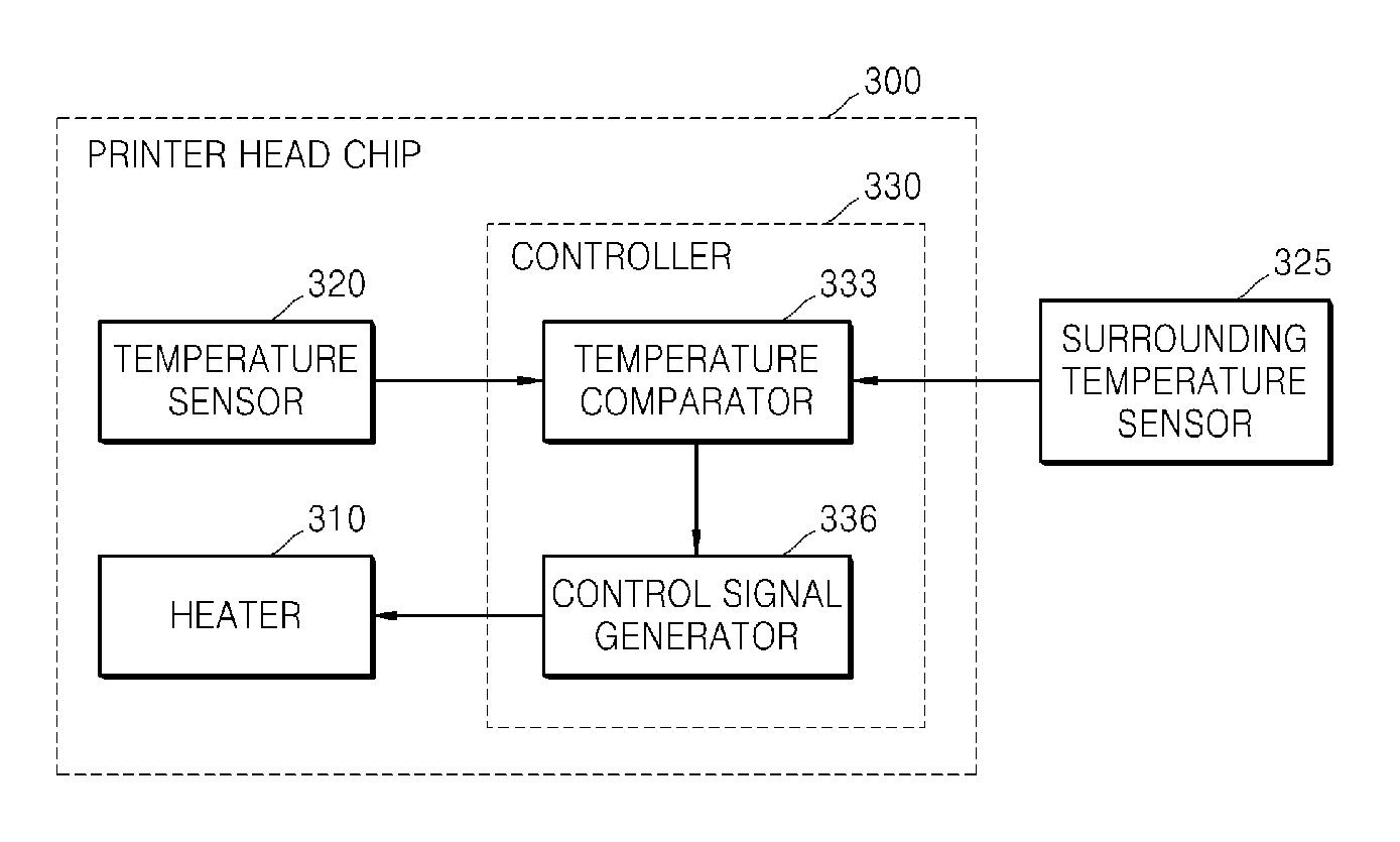
[0012] The present general inventive concept provides a method and an apparatus to control a temperature of a printer head chip in a thermal inkjet printer by providing a controller that stops a heating of the printer head chip within the printer head chip.

Problems solved by technology

When a printing resolution and a printing speed are increased in a thermal inkjet printer, the printer head chip tends to overheat.
Bubble creation within the printer head chip is directly affected by temperature, so that the overheating of the printer head chip hinders the creation of the bubbles, and ink droplets are ejected too early.
The early ejection of the ink droplets causes a printing abnormality such as an undesired ink mark on a recording medium.
Also, when the printer head chip overheats, unintended vapor bubbles are accumulated within the ink, which blocks the nozzles and hinders emission of the ink droplets.
Also, the overheating of the printer head chip shortens a life span of a heater (e.g., the thermal resistor).
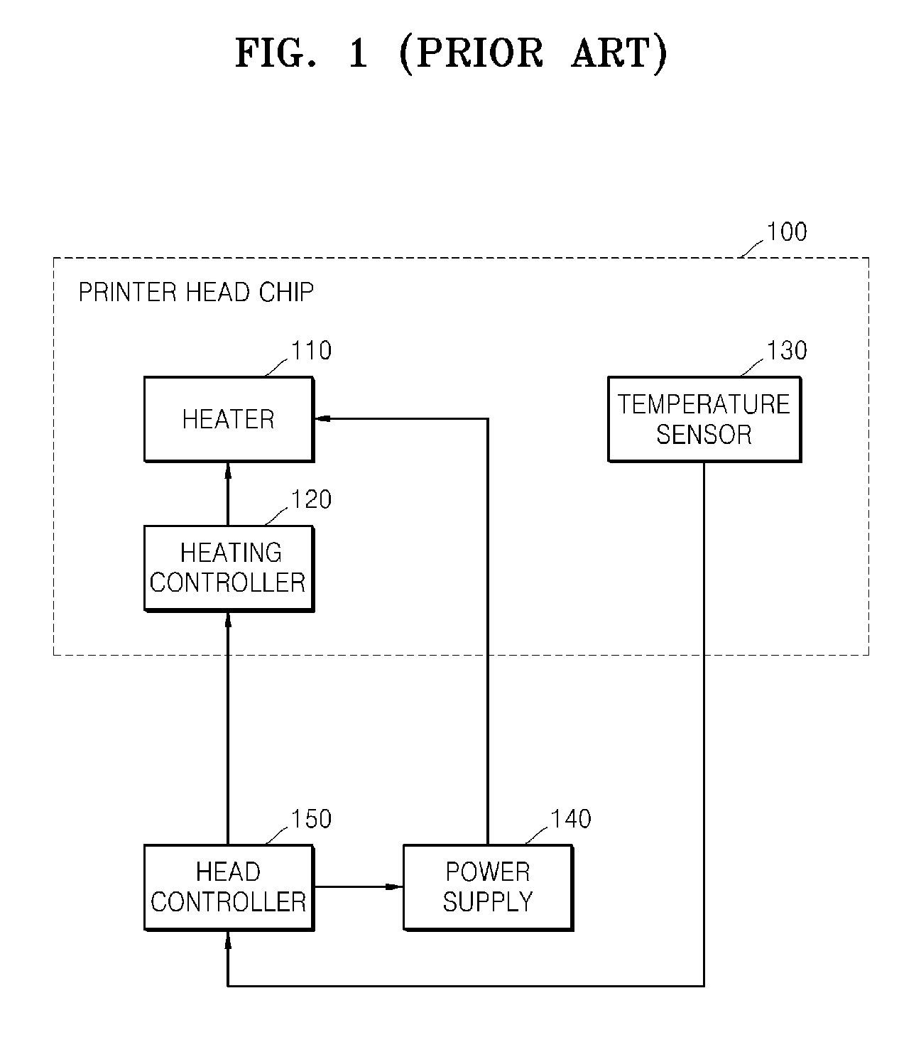
If the head controller 150 is provided outside of the printer head chip 100 for controlling the temperature of the printer head chip 100, the printer head chip 100 can be overheated and damaged, or a fire can result when the temperature within the printer head chip 100 abruptly rises or an error occurs in a main system of a printer having the head controller 150.
Accordingly, a safety problem is generated in using the conventional temperature controlling apparatus with the printer.

Method used


Image

  • Method and apparatus to control a temperature of a printer head chip
  • Method and apparatus to control a temperature of a printer head chip
  • Method and apparatus to control a temperature of a printer head chip

Examples


Embodiment Construction

[0051] Reference will now be made in detail to the embodiments of the present general inventive concept, examples of which are illustrated in the accompanying drawings, wherein like reference numerals refer to the like elements throughout. The embodiments are described below in order to explain the present general inventive concept by referring to the figures.

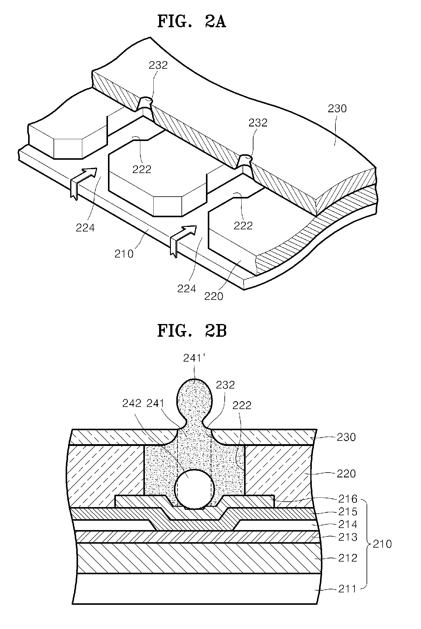
[0052]FIG. 2A is a schematic partial perspective view illustrating an example of a printer head chip. FIG. 2B is a sectional view of a vertical structure of the printer head chip illustrated in FIG. 2A. Referring to FIGS. 2A and 2B, the printer head chip includes a base plate 210 formed by stacking material layers on a substrate 211, ink chambers 222 stacked on the base plate 210, a channel plate 220 forming an ink channel 224, and a nozzle plate 230 stacked on the channel plate 220.

[0053] Ink (fluid) fills an inside of the ink chambers 222, and a heater 213 that heats the ink to create bubbles is disposed in the ink chambers...


PUM


Abstract

A method and an apparatus to control a temperature of a printer head chip. The temperature control apparatus includes a heater, a temperature sensor, and a controller. The heater heats a predetermine portion of the printer head chip. The temperature sensor senses the temperature of the printer head chip. The controller is provided in the printer head chip and provides a control signal to the heater according to the sensed temperature. Accordingly, damage to the printer head chip can be prevented and safety in using the printer can be guaranteed. Also, ink droplets can be accurately ejected from the printer head chip such that printing quality is improved and a life span of the heater is extended.

Description

CROSS-REFERENCE TO RELATED APPLICATIONS [0001] This application claims the benefit of Korean Patent Application No. 2005-52535, filed on Jun. 17, 2005, in the Korean Intellectual Property Office, the disclosure of which is incorporated herein in its entirety by reference. BACKGROUND OF THE INVENTION [0002] 1. Field of the Invention [0003] The present general inventive concept relates to an image-forming apparatus, and more particularly, to a method and an apparatus to control a temperature of a printer head chip provided in a thermal inkjet printer. [0004] 2. Description of the Related Art [0005] Inkjet printers can be classified as a continuous injection type or a drop-on-demand (DOD) type according to an injection method thereof. The DOD type can be further classified as a type that uses a piezoelectric actuator or a thermal type that uses bubbles to eject ink. The thermal type creates bubbles on a surface of a thermal resistor using heat generated by a current that flows and is d...

Claims


Application Information

Patent Timeline
Patent Type & Authority Applications(United States)
IPC IPC(8): B41J29/38
CPCB41J2/04515B41J2/04528B41J2/0458B41J2/04563B41J2/04553B41J29/393
Inventor HAN, CHUN-KU
Owner SAMSUNG ELECTRONICS CO LTD
Learn More