Individual packaging case for objects with fracture risk

Active Publication Date: 2006-12-21
ROESLER PETER
View PDF5 Cites 34 Cited by
  • Summary
  • Abstract
  • Description
  • Claims
  • Application Information

AI Technical Summary

Benefits of technology

[0010] The invention therefore has the object of designing an individual packaging case for objects with fracture risk of the aforementioned type in such a way that in the packaged state, the object with fracture risk is held securely without vibration, is protected against fracture, and is able to be removed from the packaging case with particularly good operational safety.
[0014] In an example, it is important that the area of the receiving groove (e.g., about the lower third of the length of the receiving groove) contains a crosscut interrupting the receiving groove and cut into the holder perpendicularly to the receiving groove in order to form a pivot bearing for the holder such that the receiving groove is interrupted and the holder is divided into an upper part and a lower part (or a base) pivotably attached thereto. The connection between the upper part and the lower part of the holder is preferably generated by a film hinge constructed in a horizontal pivoting axis at the rear side of the holder. This makes it possible to fold the packaging case over. When the description of the location talks about a “horizontal axis,” it is assumed that the receiving groove is oriented in a vertical direction In different situations, of course, the description of locations applies in an analogous fashion.
[0016] In another example of the embodiment, the holder is constructed in two parts comprising an upper part, a lower part or a base, and an inserted bending metal part disposed at the rear wall in the area of the crosscut separating the upper part from the lower part, the bending metal part connecting the upper and the lower parts and there forming the pivoting axis. By disposing a crosscut and a film hinge disposed thereon, however, the construction of the holder from a synthetic material part leads to the achievement of optimally little tool use with optimally low cost so that the further description describes this embodiment in more detail. It is of importance that the construction of the holder in the manner described generates substantial advantages in relation to the prior art. Since the object with fracture risk to be held is placed into a receiving groove in its entire length, an advantage of the claimed invention is that the object is also supported effectively against vibrations and fracture along its entire length in the receiving groove. In the simplest case, the holding fixture of the object with fracture risk in the receiving groove is designed in such a way that the object is held in the receiving groove in a way to be easily slidable and that the upper end of the holder is covered by a protective cap encircling the holder on four sides, thereby providing a circumferential protection for the holder. The object cannot be moved forward out of the receiving groove in the direction of the longitudinal extension thereof without force until the protective cap is pulled off the holder. The object thus is held freely slidably in the receiving groove and can be shaken out of the receiving groove after the protective cap is pulled off. The object then drops out forward in the direction of the longitudinal extension of the receiving groove, but can also be removed in the forward direction out of the receiving groove, which is open toward the front.
[0023] In a second example of an embodiment, the novel movement relates to the fact that the pivot bearing is furnished with a pivot safety device which has to be overcome (possibly by a crack sound) at the time of the initial opening of the pivot bearing, wherein after overcoming the safety device, the pivot bearing can be pivoted. An advantage of this embodiment lies in the fact that during manufacture of a holder of this type, the holder is constructed with a basic rigidity without which the danger would exist that the upper part unintentionally pivots away from the lower part. A further advantage of this embodiment lies in the fact that during initial opening of the packaging case (e.g. when pulling off the protective cap) the device can be operated with great safety. When the cap is pulled off of containers in the prior art, the cap may be tilted, thereby causing the upper part unintentionally to be pivoted in relation to the lower part in the area of the pivoting axis, whereby the object with fracture risk is unintentionally lifted out of its receiving groove and, for example, is damaged on the interior side of the protective cap to be pulled off. The present invention eliminates this risk by providing a container that retains the basic rigidity during initial pull-off of the protective cap so that even when the protective cap is pulled off by tilting, the danger does not arise that the upper part is already pivoted unintentionally in relation to the lower part. In an example of the claimed invention, the so-called “cracking” of the pivot joint occurs, wherein two knob connections of synthetic material are preferably disposed in the pivoting area of the pivot joint, the connections being destroyed during initial pivoting of the pivot joint in order to achieve the described “crack” effect. An additional advantage of the claimed invention is that the so-called “crack” safety device ensures that the packaging case of the holder has not yet been opened. The object can practically be removed from the holder only by pivoting the upper part away from the direction of the lower part, and once the “crack” joint has been destroyed, it is easy to recognize thereafter that the object has already been removed once before.

Problems solved by technology

Individual packaging cases of this type have proven themselves, though they have the disadvantage of being relatively complicated to handle.
Since the object with fracture risk protrudes upwardly and self-containedly from the receiving bore in the base, the danger exists that if the protective cap is pulled off at a slant, the protective edge may touch the object with fracture risk and may even, in the worst case, break off the object.
A further disadvantage lies in the fact that the object is not optimally protected from fracture due to the self-contained fixation of the object with fracture risk.
If, for example, a packaging case of this type is dropped to the floor unintentionally, the danger exists that the object may break off due to the self-contained fixture.
The third disadvantage lies in the fact that the object has to be manually removed from the container by the very place that needs to be protected, namely, for example, in the area of the place with fracture risk, which again is associated with the danger of damaging the object.
The strong holding forces, however, are disadvantageous, particularly when the object with fracture risk has to be removed from the base after the protective cap is pulled off, because a considerable manual or traction force needs to be exerted on the object with fracture risk in order to pull the object upward out of its clamping fixture.
The relatively strong traction forces also create the danger that the object with fracture risk is buckled or tilted, which again creates the danger of damaging the object.
An additional disadvantage of the packaging case known in the art lies in the fact that it is not possible to directly insert the object, for example, into a tool holding fixture after pulling off the protective cap without touching the object with a hand.
This handling system is not safe in operation and leads to damage of objects, particularly when the objects are of a thin and / or fragile construction.

Method used


Image

  • Individual packaging case for objects with fracture risk
  • Individual packaging case for objects with fracture risk
  • Individual packaging case for objects with fracture risk

Examples


Embodiment Construction

OF EMBODIMENTS OF THE INVENTION

[0046] In a preferred example of an embodiment the invention, the holder 1 is manufactured of a synthetic material, although the invention is not limited to this. It is also possible to provide that the holder 1 be manufactured of a metal material, in particular, a light metal alloy, or wood, or a composite material consisting of several material composites.

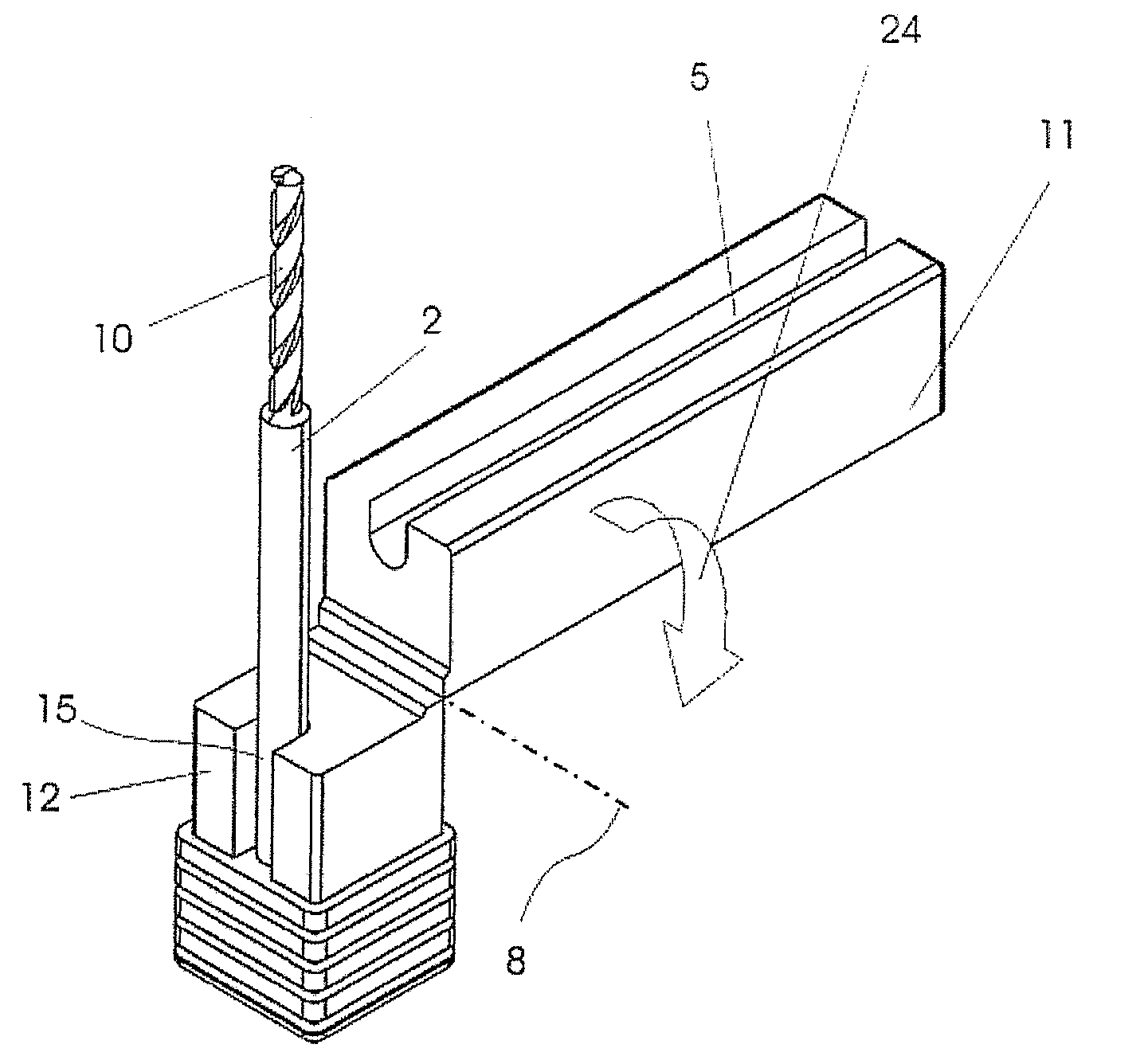
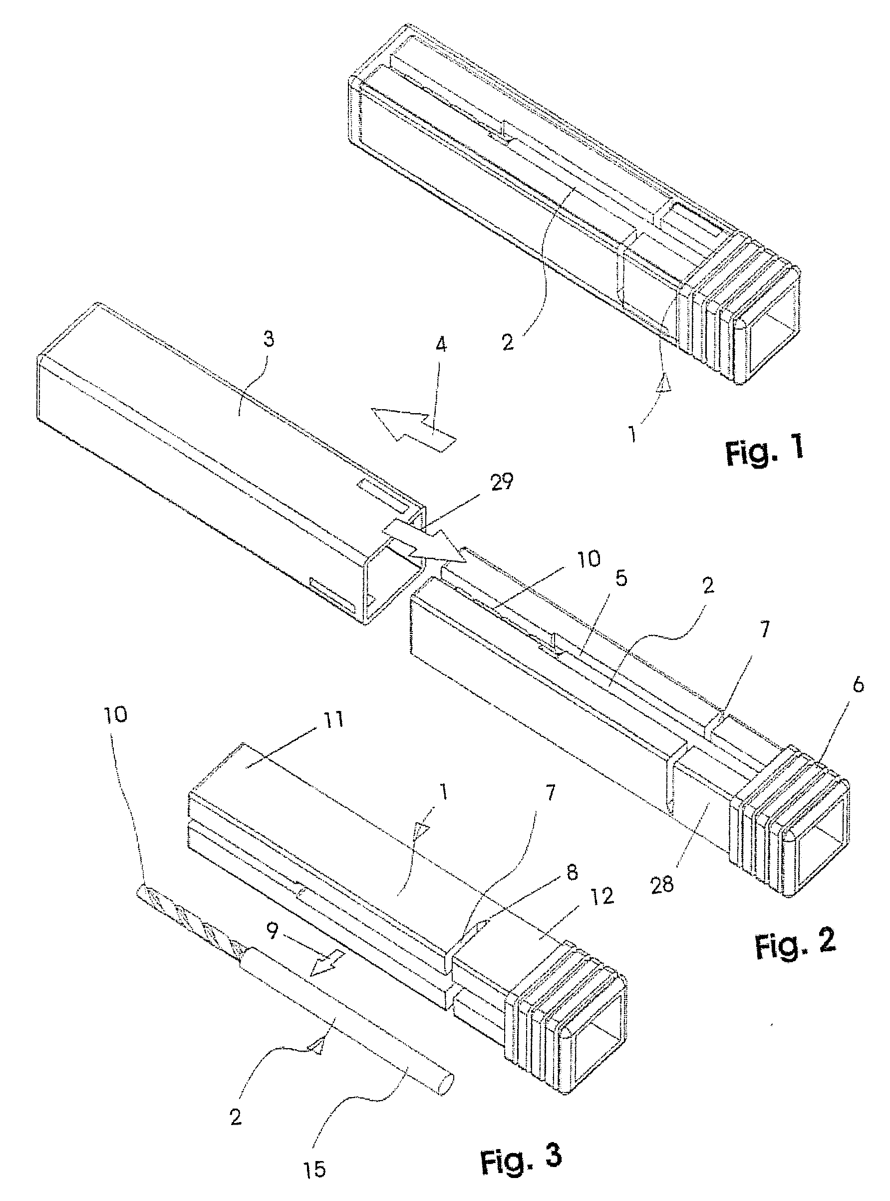
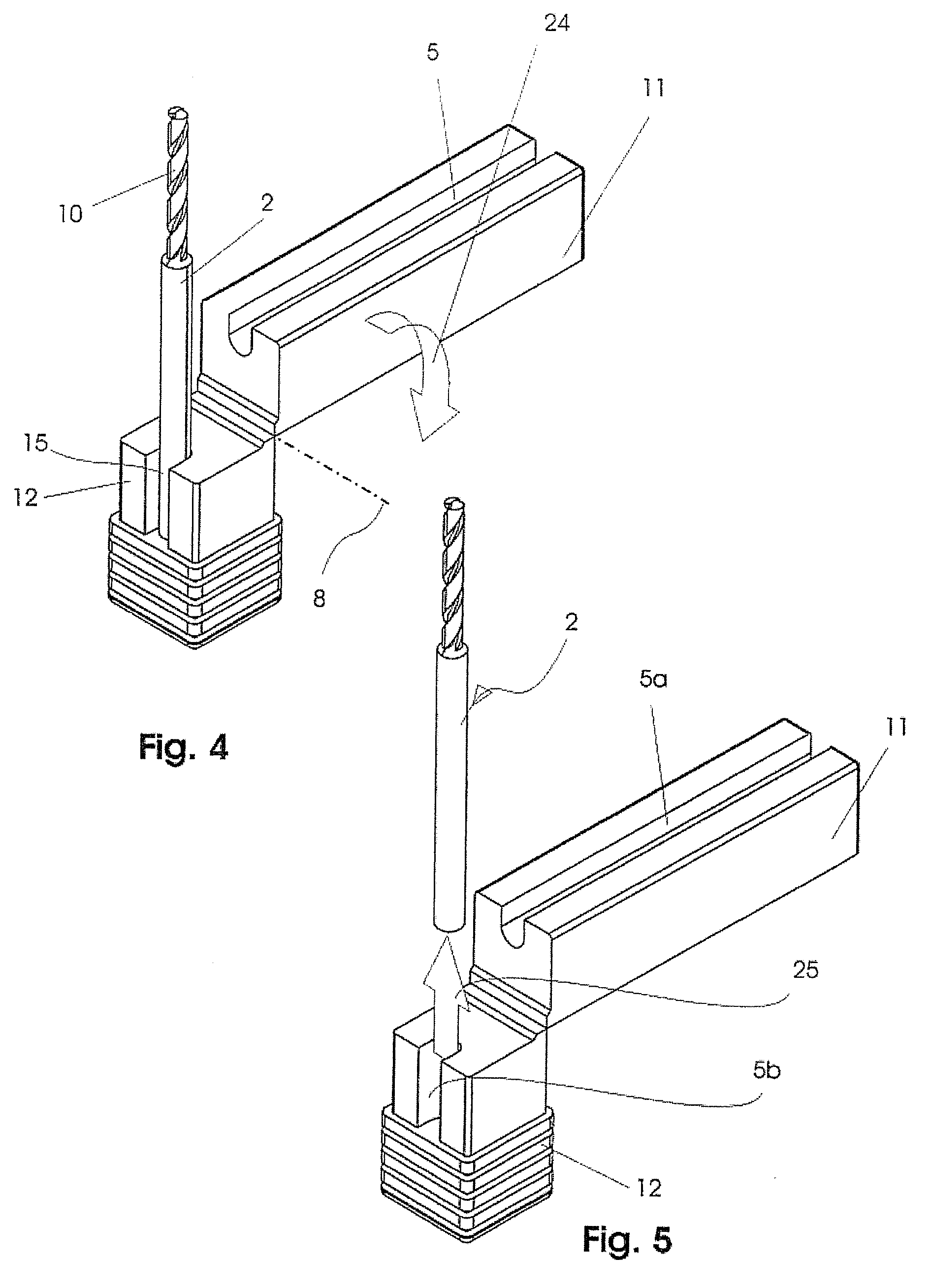
[0047] In an embodiment described below, the holder 1 comprises an injection-molded part made of synthetic material and serves to receive an object 2 with fracture risk comprising in the preferred embodiment a very filigree drill for dental medicine. In an example, the object 2 has a bit 10 with fracture risk.

[0048] A receiving groove 5 extending in a longitudinal direction is formed into the holder 1, the receiving groove receiving the object 2, wherein the reception of the object 2 in the receiving groove 5 can occur in various embodiments according to at least the general description:

[0049] 1)...


PUM


Abstract

The invention relates to an individual packaging case for objects with fracture risk wherein the individual packaging case comprises a base with an open, upward-pointing receiving bore, into which the shank of the object with fracture risk is inserted and self-containedly protrudes from the upward-open receiving bore in the base and wherein the part with fracture risk of the object is protected by means of a protective cap pushed onto the base from above. The invention is characterized in that the novel packaging case can be folded over an axis running perpendicular to the longitudinal axis and that due to the folding, the object to be protected becomes at least partially freely accessible.

Description

CLAIM OF PRIORITY [0001] This invention claims the benefit of German Application No. 10 2005 022 385.0, filed on May 14, 2005. FIELD OF THE INVENTION [0002] The subject of the claimed invention is an individual packaging case for objects with fracture risk, and specifically a packaging case comprising a pivoting axis that folds and makes the object to be protected at least partially accessible. BACKGROUND OF THE INVENTION [0003] The possibility of storing objects with fracture risk in an individual packaging case in such a way that there is a base of synthetic material with an open, upward-pointing receiving bore into which the shank or foot part of the object with fracture risk is inserted, is known to the art. The part of the object with fracture risk self-containedly protrudes through the upward-open receiving bore in the base and is protected from fracture by a protective cap pushed onto the base from above. In order to remove the object from the individual packaging case, first...

Claims


Application Information

Patent Timeline
IPC IPC(8): B65D81/02A45C11/26
CPCB25H3/023B65D85/30B65D85/20B65D81/02
Inventor ROESLER, PETER
Owner ROESLER PETER
Why Eureka
Try Eureka