
Connecting structure of rotary connector and steering angle sensor

Inactive Publication Date: 2006-12-21
ALPS ALPINE CO LTD
View PDF2 Cites 11 Cited by
  • Summary
  • Abstract
  • Description
  • Claims
  • Application Information

AI Technical Summary

Benefits of technology

[0013] According to the solving means of the invention, the intermediate elastic member is interposed between the first rotor member and the second rotor member. The intermediate member urges the first rotor member and the second rotor member a direction that they separate from each other. Both rotor members are positioned in the rotation direction as the connecting protrusions (or connecting notched portions) of the first and second rotor members are engaged with the engaging notched portions (or engaging protrusions) of the intermediate elastic member. Therefore, a backlash can be suppressed between both of the rotor members, and thus stable detection signals can be obtained from the steering angle sensor.
[0014] In addition, since it is unnecessary to provide a coil spring for preventing a backlash, vibration noise, a so called spring noise, can be reduced. Therefore, improvements can be achieved in terms of noise reduction. Further, as at least some of the plurality of engaging notched portions (or connecting notched portions) are formed in an elongated hole shape, the corresponding connecting protrusions (or engaging protrusions) are engaged with the engaging notched portions (or connecting notched portions) in a state movable in a radial direction of the intermediate elastic member. For this reason, the central axis of the first rotor member is allowed to deviate from the central axis of the second rotor member, and the rotary connector which requires a relatively large clearance is connected to a highly accurate steering angle sensor, and thus both of the rotor members can be smoothly rotated. Furthermore, since the intermediate elastic member regulates the second rotor member of the steering angle sensor in the axis line direction with respect to the fixing member, it is possible to easily realize the structure in which the second rotor member is rotatably supported by the fixing member.
[0016] Preferably, the pair of engaging notched portions to be engaged with the connecting protrusions of the first rotor member is formed in an elongated hole shape. Therefore, it is possible to easily ensure a required clearance in the rotary connector. Preferably, one of the pair of engaging notched portions is formed between two elastic arms, the two elastic arms elastically clamping the connecting protrusion from the circumferential direction of the intermediate elastic member. Therefore, it is possible to reliably prevent a backlash in the rotation direction.
[0017] In the above-described structure, preferably, micro spikes are formed on a plurality of places of the top and bottom surfaces of the intermediate elastic member, the micro spikes are in point-contact with the first rotor member or the second rotor member; therefore, intermediate elastic member is prevented from being adhere onto both of the rotor members, and thus the intermediate elastic member is prevented from hindering a relative movement of both of the rotor members in the radial direction.
[0018] In addition, in the above-described structure, preferably, the second rotor member is formed of a synthetic resin molding product in which the code plate is integrated to the outer peripheral surface of the hollow shaft portion. In this case, since the intermediate elastic member regulates the second rotor member of the steering angle sensor in the axis line direction with respect to the fixing member, it is possible to reduce the number of parts and the man-hour for assembling by using the second rotor member formed by integrating the code plate to the outer peripheral surface of the hollow shaft portion.

Problems solved by technology

Consequently, operability in assembly deteriorates when the rotary connector and the steering angle sensor are formed as one unit, and noise such as a so called spring noise, is generated due to vibration of the coil spring while driving the vehicle.
Therefore, at least three members (code plate and the pair of separate members) are required to form an integrated product including the code plate and the rotor member, which leads to an increase in the number of parts of the steering angle sensor, thereby increasing cost.

Method used


Image

  • Connecting structure of rotary connector and steering angle sensor
  • Connecting structure of rotary connector and steering angle sensor
  • Connecting structure of rotary connector and steering angle sensor

Examples


Embodiment Construction

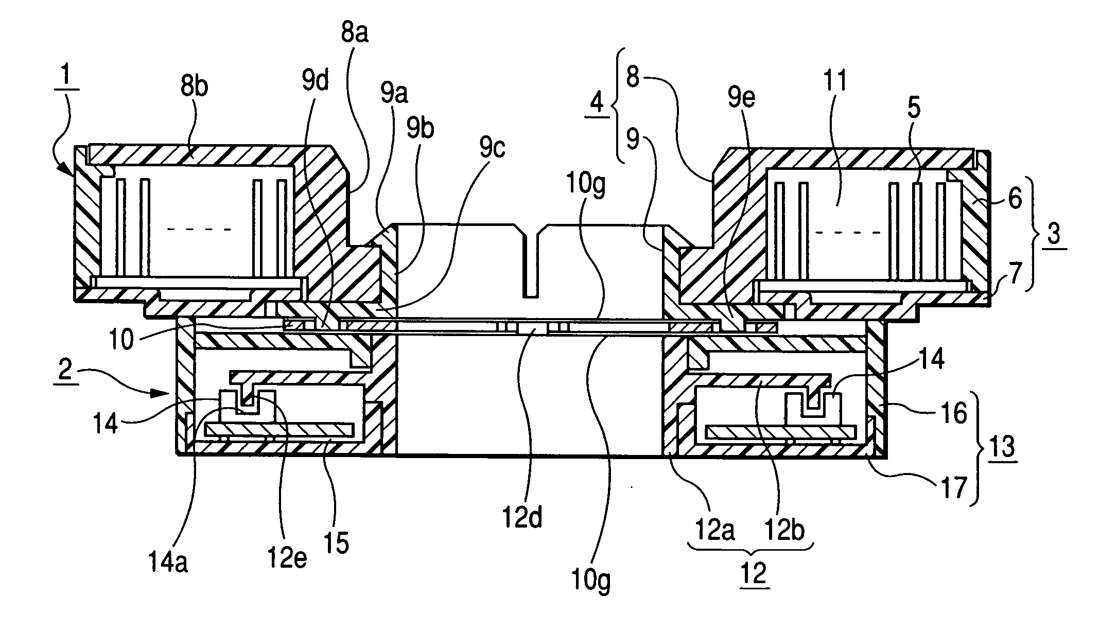
[0023] A preferred embodiment of the present invention will be described with reference to the accompanying drawings. FIG. 1 is a cross-sectional view illustrating a connecting unit of a rotary connector and a steering angle sensor according to the embodiment of the present invention. FIG. 2 is an exploded perspective view of the connecting unit. FIG. 3 is a plan view of an intermediate elastic member provided in the connecting unit. FIG. 4 is a cross-sectional view of the intermediate elastic member.

[0024] The connecting unit according to the embodiment is composed of a rotary connector 1, a steering angle sensor 2, and an intermediate elastic member 10. The rotary connector 1 and the steering angle sensor 2 are integrally built in a steering apparatus of a vehicle in which they are vertically laid on each other with the intermediate elastic member 10 interposed therebetween.

[0025] The rotary connector 1 is used as the electrical connecting means for an air bag system mounted on ...


PUM


Abstract

In the connecting structure of a first rotor member (rotor housing) of a rotary connector and a second rotor member (rotary member) of a steering angle sensor is provided. An intermediate elastic member is interposed between both rotor members and in a clamped state, connecting protrusions and of the first rotor member are engaged with a pair of engaging notched portions of the intermediate elastic member, and connecting protrusions of the second rotor member are engaged with another pair of engaging notched portions. A line connecting the pair of engaging notched portions is orthogonal to a line connecting the pair of engaging notched portions. In addition, the engaging notched portions are formed in an elongated hold shape, and thus the first rotor member is allowed to move in the radial direction of the intermediate elastic member.

Description

BACKGROUND OF THE INVENTION [0001] 1. Field of the Invention [0002] The present invention relates to a connecting structure of a rotary connector built in a steering apparatus of a vehicle, [0003] 2. Description of the Related Art [0004] A rotary connector generally includes a stator member, a rotor member rotatably connected to the stator member, a flexible cable held and wound in an annular space defined between the stator member and the rotor member, and as the rotor member is rotated in accordance with the steering wheel, the flexible cable is wound or unwound in the annular space. Here, a relatively large clearance (in an in-plane direction orthogonal to a rotation axis) is formed between the rotor member and the stator member of the rotary connector. Accordingly, the rotor member can be stably rotated in accordance with the steering wheel. In the meantime, a steering angle sensor includes a fixing member, a rotor member having a code plate that is rotatably connected to the fi...

Claims


Application Information

Patent Timeline
IPC IPC(8): G01B21/22
CPCB60R16/027H01R35/025B62D15/022B62D15/0215H01R35/00H01R39/00
Inventor ARAKI, JUNJISANO, TADASHI
Owner ALPS ALPINE CO LTD
Learn More