
Photodynamic therapy equipment, method for controlling photodynamic therapy equipment and method of photodynamic method

Inactive Publication Date: 2006-12-14
TERUMO KK
View PDF19 Cites 37 Cited by
  • Summary
  • Abstract
  • Description
  • Claims
  • Application Information

AI Technical Summary

Benefits of technology

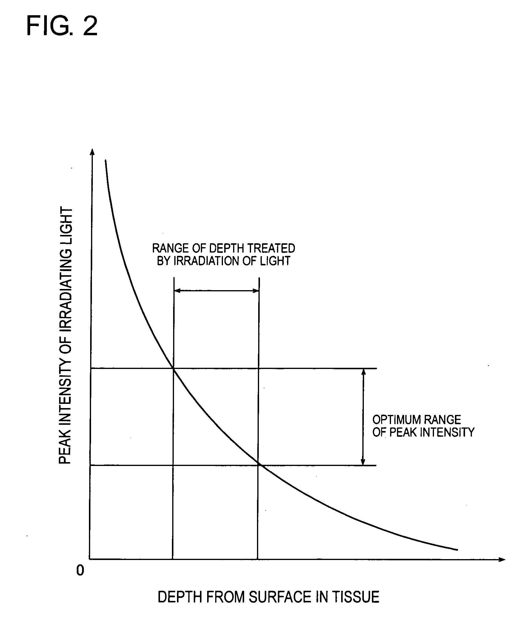
[0014] Further we have found that the peak intensity of the laser beam could be maintained within the range of the high therapeutic efficiency of PDT in the certain range of the depth and the PDT therapy could be achieved in that depth. Contrary to these findings, it is suggested that when the PDT therapy is intended to perform effectively at the fixed depth, an effect of PDT is made to increase upward by adjusting the peak intensity of the irradiating laser beam when the laser beam is reached to that depth.
[0015] Further, we have studied the principle of PDT therapy, in which the energy of the PDT drug excited by the laser irradiation was transferred to oxygen atoms in the tissues to generate active oxygen causing to damage surrounding cells, and the PDT therapy, in which the irradiation depth of laser beam could be controlled.

Problems solved by technology

Consequently, there was a problem that even if the laser of this wavelength range was irradiated, the beam could only arriving at the depth to several millimeters from the surface, and the deep-lying lesioned part could not be treated.
There was further problem that drugs developed in the early stage exhibited no good excretion from the body and photosensitivity complications (sunburn symptom).
However, although such the second generation drug for PDT was developed, the technologies for controlling parameters for laser irradiation have not established and matters in question such as optimum intensity of laser irradiation and irradiation time have not been elucidated.
For that reason, in case of normal surface region with deep-lying lesioned part, highly invasive treatment with irradiating the laser beam directly to the lesioned part by inserting the laser irradiation part into the tissue was only studied, and a development of PDT with low invasive method for damaging the deep-lying lesion has been thought to be difficult.

Method used


Image

  • Photodynamic therapy equipment, method for controlling photodynamic therapy equipment and method of photodynamic method
  • Photodynamic therapy equipment, method for controlling photodynamic therapy equipment and method of photodynamic method
  • Photodynamic therapy equipment, method for controlling photodynamic therapy equipment and method of photodynamic method

Examples


example 1

Control of Treatment Depth on Light Irradiation Condition Using Arteriosclerotic Athero Model

[0136]FIG. 7 is a graphical representation showing peak intensity and repetition frequency dependency of PDT effect. FIG. 8 is a graphical representation showing relationship between drug breaching and peak intensity. FIG. 9 is a graphical representation showing changes of rate of cell death when irradiation energy is changed.

[0137] In a treatment for attempting reduction of arteriosclerotic stenosed volume and maintaining perfusion blood flow rate, a method for controlling treatment depth by changing the light irradiation condition (peak intensity and frequency) for treating inside of athero alone and prevent damage of penumbral tissue was examined.

[0138] With regard to arteriosclerotic athero model, mouse derived macrophage like cell J774.1 was used. PDT was performed after contacting with the second generation photosensitive substance ATX-S10 (ATX-S10 Na(II) (K.K. Hikari Chemical Lab....

example 2

Control of Superficial Part Preservation Range 1

[0147]FIG. 10 is a graphical representation showing measurement result of rate of cell death to depth in each pulse energy density when pulse number is maintained constant.

[0148] In example 2, a rate of cell death on various depth with different pulse energy density under constant pulse number of irradiating light was measured.

[0149] 10,000 pulses were irradiated under the condition of pulse energy density ranging from 0.3 mJ / cm2 to 9.5 mJ / cm2, with constant pulse width and repetition frequency of the irradiated pulsed light. The rate of cell death on the depth was measured. Result is shown in FIG. 10.

[0150] In the low pulse energy density at the range from 0.3 mJ / cm2 to 1.5 mJ / cm2, the rate of cell death was attenuated almost uniformly from the irradiated surface to the depth. Contrary to that, in the irradiation at pulse energy density 2.5 mJ / cm2 or more, significantly low range of rate of cell death was remained in the superfic...

example 3

Control of Superficial Part Preservation Range 2

[0154]FIG. 11 is a graphical representation showing measurement result of rate of cell death to depth when amount of total irradiating energy is maintained constant.

[0155] In example 3, the rate of cell death to depth in each different pulse energy density with maintaining the total irradiation energy of irradiating light to be constant was measured.

[0156] Referring to the above example 2, an example of the superficial preservation treatment, when amount of the total irradiation energy is to be constant, is shown.

[0157] Irradiation was continued until the total amount of irradiation energy is reached to 40 J under the condition of pulse energy density ranging from 2 mJ / cm2 to 9.5 mJ / cm2, i.e. the range to form the superficial preservation range, with constant pulse width and repetition frequency of the irradiated pulsed light. The rate of cell death on the depth was measured. Result is shown in FIG. 11.

[0158] High rate of cell de...


PUM


Abstract

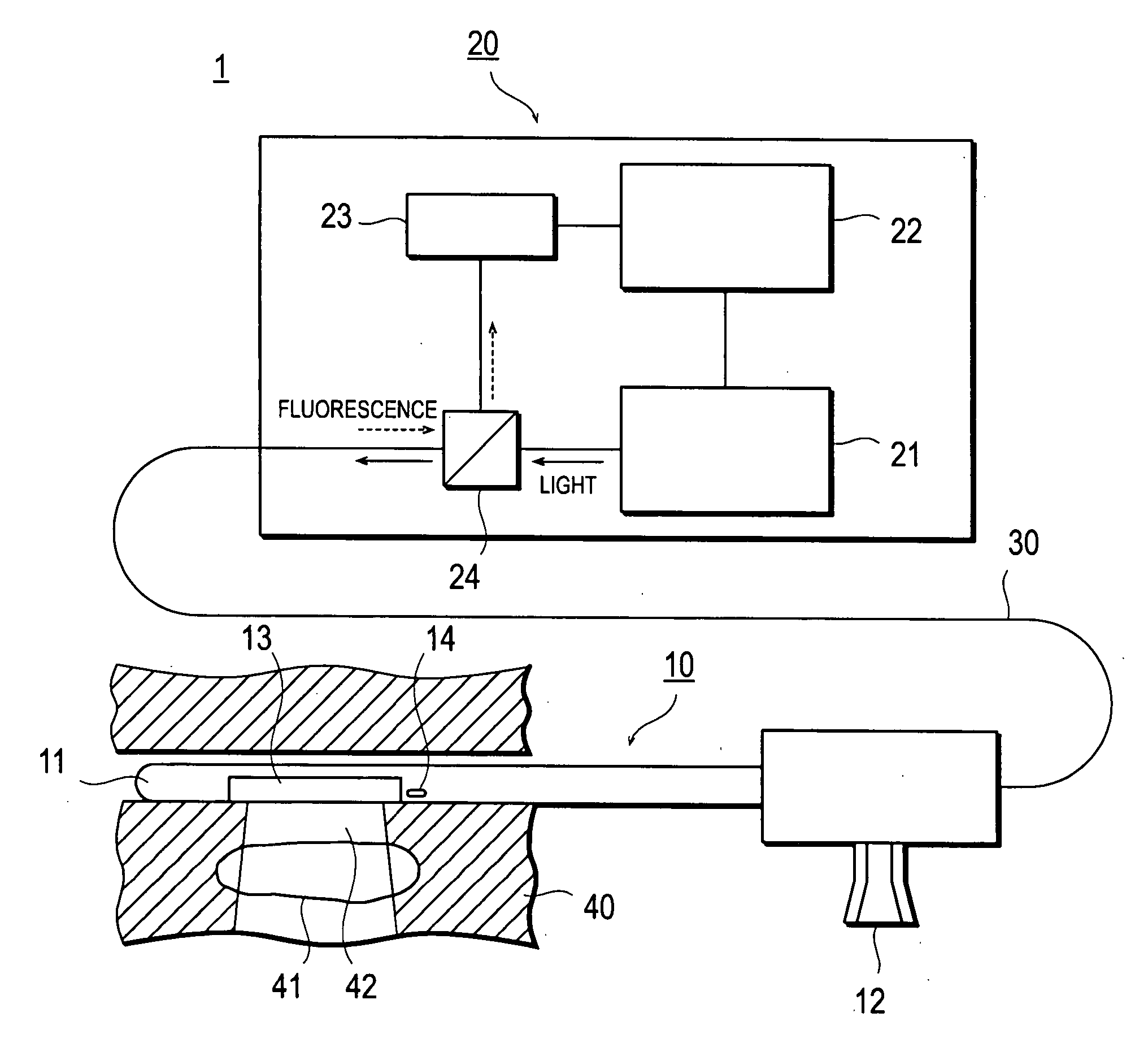
The invention provides PDT equipment which can absolutely treat the deep lesioned part with preserving the superficial membrane of the healthy region. Photodynamic therapy equipment 1 for treating lesioned part by using a photosensitive substance, which is activated by the light having a peak intensity of a predetermined range but is almost not activated by the light having the peak intensity out of the predetermined range, equipped with an irradiation means 13 irradiating into the body a pulsed light of the wavelength having the potential for activating the photosensitive substance, and a control means 22 controlling the peak intensity of the light irradiated by the irradiation means, and the control means 22 allows the irradiation means 13 to irradiate the light having the high peak intensity in order that the light arriving at the deep-lying lesioned part 41 is to achieve the peak intensity of the predetermined range.

Description

TECHNICAL FIELD [0001] The present invention relates to photodynamic therapy equipment, a method for controlling thereof and a method of photodynamic therapy. More particularly, the present invention pertains the photodynamic therapy (superficial lesion preserving therapy) equipment, which can damage the deep-lying lesioned part with preserving the normal superficial region, without damaging, covered on the lesioned part in the treatment of the deep-lying lesioned part in the body, the method for controlling thereof and the method of photodynamic therapy. BACKGROUND ART [0002] Photochemical therapy (PDT; also designates as photodynamic therapy) is considering the possibilities of applying to various treatments in addition to the endoscopic phototherapy of early carcinoma. PDT is a therapeutic method, in which the photosensitive substance (photo-sensitizer) such as certain types of porphyrin derivatives is administered by a method of intravenous injection, subjected to adsorb and acc...

Claims


Application Information

Patent Timeline
IPC IPC(8): A61N5/06
CPCA61N5/062A61N5/0601
Inventor ARAI, TSUNENORIOHMORI, SAYAKAYANAGIHARA, TAKESHI
Owner TERUMO KK
Learn More