
Optical transmitter and optical receiver

a technology of optical transmitter and optical receiver, which is applied in the direction of diversity/multi-antenna system, electromagnetic wave modulation, modulation, etc., can solve the problem of inability to generate a replacement bit stream having a mark ratio of 20%, increase in redundancy, and inability to fine-tune the luminance of light emitting elements with mark ratio control. the effect of fine-tuned adjustment of the luminance of light emitting elements and suppressing an increase in redundancy

Inactive Publication Date: 2006-12-07
KYOCERA CORP
View PDF3 Cites 23 Cited by
  • Summary
  • Abstract
  • Description
  • Claims
  • Application Information

AI Technical Summary

Benefits of technology

[0009] The invention was devised to solve the problems discussed above, and one of its objects is to provide an optical transmitter and an optical receiver that enable fine-tuned adjustment of the luminance of the light emitting elements using mark ratio control while suppressing an increase in the redundancy of the bit stream.

Problems solved by technology

However, it is impossible to generate a replacement bit stream having a mark ratio of 20%.
On the contrary, fine-tuned adjustment (light control) of the luminance of the light emitting elements cannot be achieved with mark ratio control without some increase in redundancy.

Method used


Image

  • Optical transmitter and optical receiver
  • Optical transmitter and optical receiver
  • Optical transmitter and optical receiver

Examples


Embodiment Construction

[0031] One embodiment of the invention will be described with reference to the drawings.

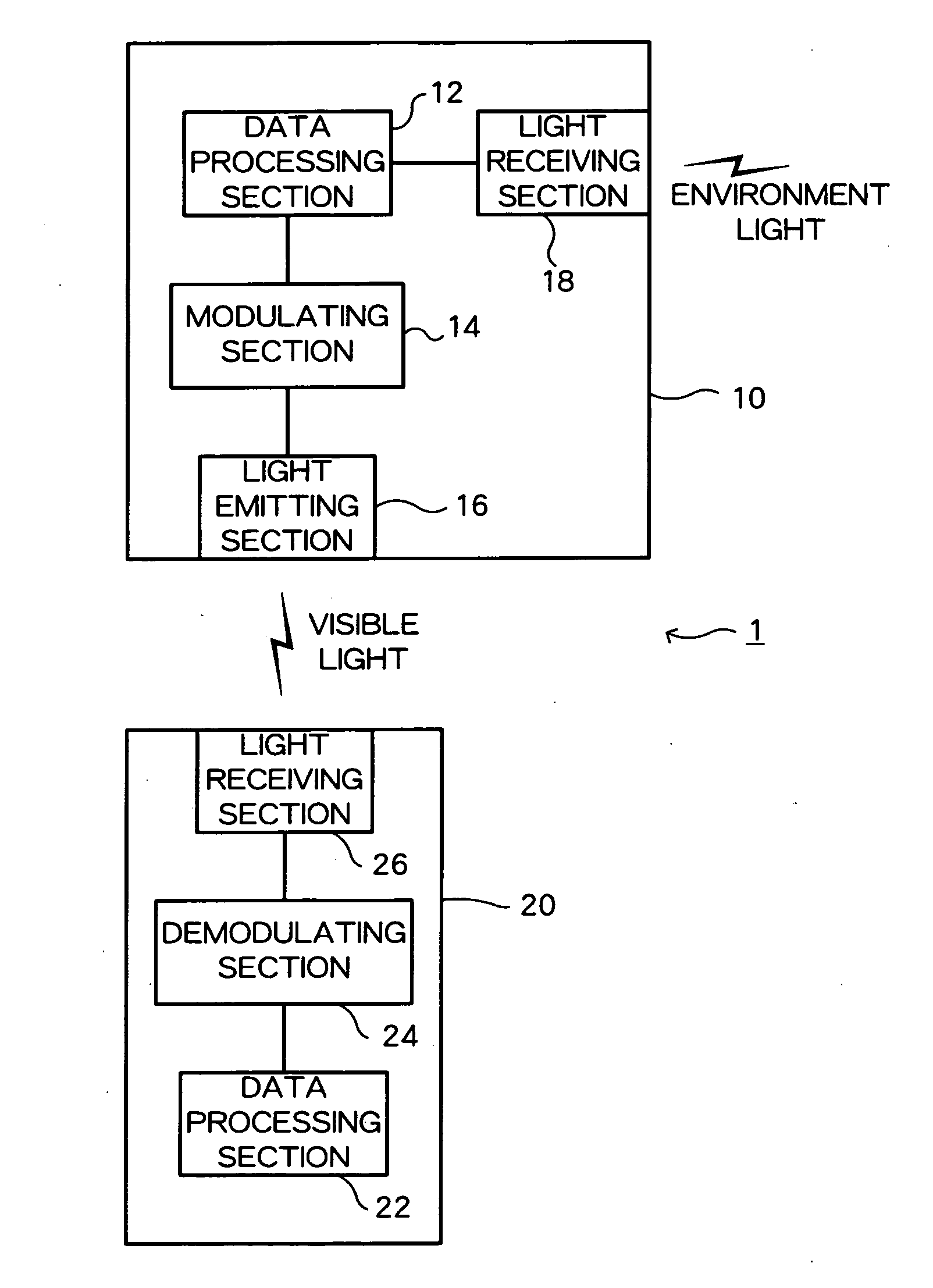
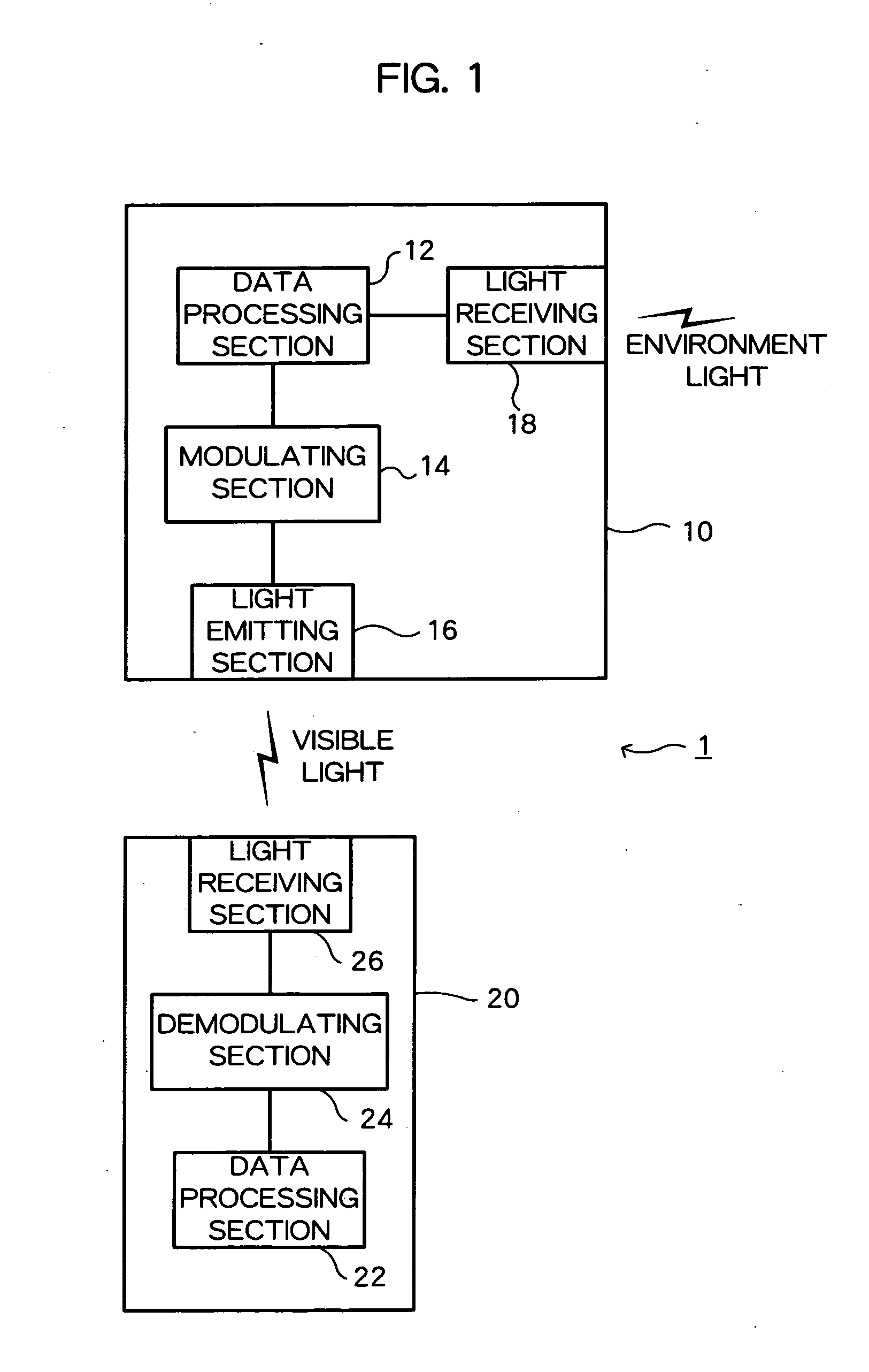
[0032]FIG. 1 is a view showing the system configuration of a visible light communications system 1 according to one embodiment. As is shown in the drawing, the visible light communications system 1 of this embodiment includes at least one optical transmitter 10 and at least one optical receiver 20, and one-way visible light communications using visible light as a communication medium are enabled by transmitting a communication signal from the optical transmitter 10 to the optical receiver 20.

[0033] The optical transmitter 10 is a visible light communications device comprising a data processing section 12, a modulating section 14, a light emitting section 16, and a light receiving section 18. The light emitting section 16 comprises light emitting elements. Normally, a large number of light emitting elements are arrayed in the light emitting section 16. The optical transmitter 10 makes communicat...


PUM


Abstract

In an optical transmitter provided with an LED that transmits a transmission bit stream as an optical signal by varying the luminance of visible light to be irradiated according to an input transmission bit stream, plural scramble data streams each having a different mark ratio are stored in a scramble data stream storage, and a light-control bit stream to which the mark ratio of the transmission bit stream is changed by performing a reversible bit operation on the transmission bit stream using a scramble data stream chosen among the stored scramble data streams. The light-control bit stream is then outputted to the LED.

Description

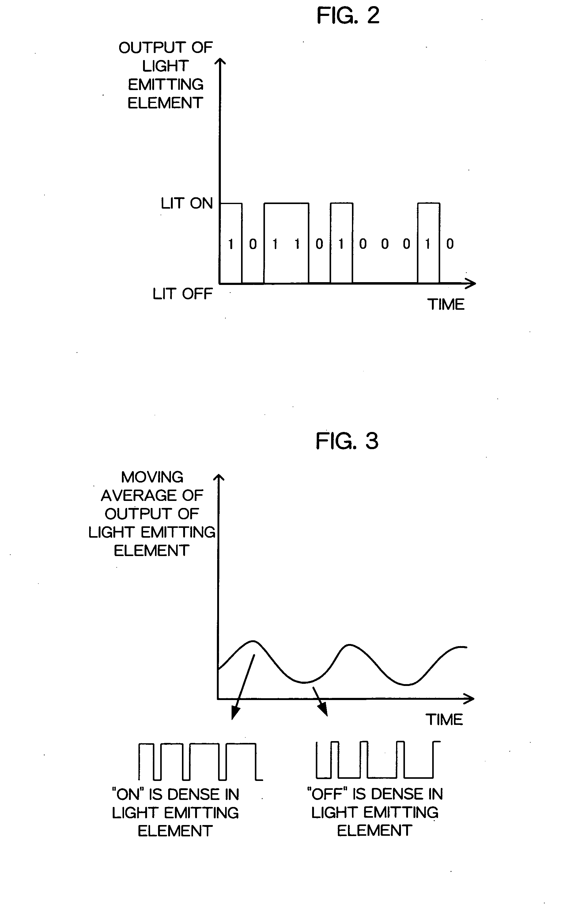
BACKGROUND OF THE INVENTION [0001] The present invention relates to an optical transmitter and an optical receiver, and for example, to a technique for controlling a mark ratio of transmission data. [0002] One type of visible light communications system for enabling communications by varying luminance of light emitting elements has the capability of controlling the luminance of the light emitting elements by controlling a mark ratio of a bit stream as communication data. The mark ratio is defined as a ratio of “1's” included in a bit stream. Because the light emitting element is ON when the bit exhibits “1” and OFF when the bit exhibits “0”, the luminance of the light emitting element can be controlled by controlling the mark ratio. [0003] An example of the luminance control is described in JP-A-2004-72365. According to the PPM control described in JP-A-2004-72365, the luminance of the light emitting element is controlled without reducing the information volume included in a bit str...

Claims


Application Information

Patent Timeline
Patent Type & Authority Applications(United States)
IPC IPC(8): H04B1/02H04B7/02H03C7/02H04B10/04H04B10/12H04B10/11H04B10/116H04B10/524H04B10/556
CPCH03D9/00H04B10/116H04B10/1141
Inventor KITAJI, MITSUHIROISHIZUKA, YUJI
Owner KYOCERA CORP
Learn More