
Optical network monitoring system and method

a network monitoring and optical network technology, applied in the field of computer networks, can solve the problems of data that may otherwise be received and monitored by a service provider server or other network component, may be subject to modification, and the traditional network monitoring approach may lose applicability in conjunction with facilitating legal intercept or other network monitoring,

Inactive Publication Date: 2006-11-30
CISCO TECH INC
View PDF9 Cites 14 Cited by
  • Summary
  • Abstract
  • Description
  • Claims
  • Application Information

AI Technical Summary

Problems solved by technology

However, monitoring such optical networks may become particularly problematic in view of recent developments.
Traditional network monitoring approaches may, however, lose applicability in conjunction with facilitating legal intercept or other network monitoring especially in the case of optical networks.
For example, data that may otherwise be received and monitored by a service provider server or other network component may be subject to modification, whether through tampering, side effects of the network component operation or other causes, elsewhere in the network, and thus insufficient for legal intercept purposes.
Cutting an applicable optical network data path and attaching an off-the-shelf optical splitter for connection to some monitor at some point may also be problematic.
Unfortunately, the 60 percent or less optical signal level that remains for completing the transmission may be insufficient for a particular optical coupling path or may render the monitoring (e.g., legal intercept) discoverable by a monitored suspect.
To make matters more difficult, a mis-connection may well result in diverting the 60 percent signal and transmitting the 40 percent signal.
Worse yet, the mis-connection may result in initial, intermittent or other discontinuous transmission that may hinder discovery of the error, among other problems.

Method used


Image

  • Optical network monitoring system and method
  • Optical network monitoring system and method
  • Optical network monitoring system and method

Examples


Embodiment Construction

[0028] In the description herein for embodiments of the present invention, numerous specific details are provided, such as examples of components and / or methods, to provide a thorough understanding of embodiments of the present invention. One skilled in the relevant art will recognize, however, that an embodiment of the invention can be practiced without one or more of the specific details, or with other apparatus, systems, assemblies, methods, components, materials, parts, and / or the like. In other instances, well-known structures, materials, or operations are not specifically shown or described in detail to avoid obscuring aspects of embodiments of the present invention.

[0029] A “computer” for purposes of embodiments of the present invention may include any processor-containing device, such as a mainframe computer, personal computer, laptop, notebook, microcomputer, server, personal data manager or “PIM” (also referred to as a personal information manager or “PIM”) smart cellular...


PUM


Abstract

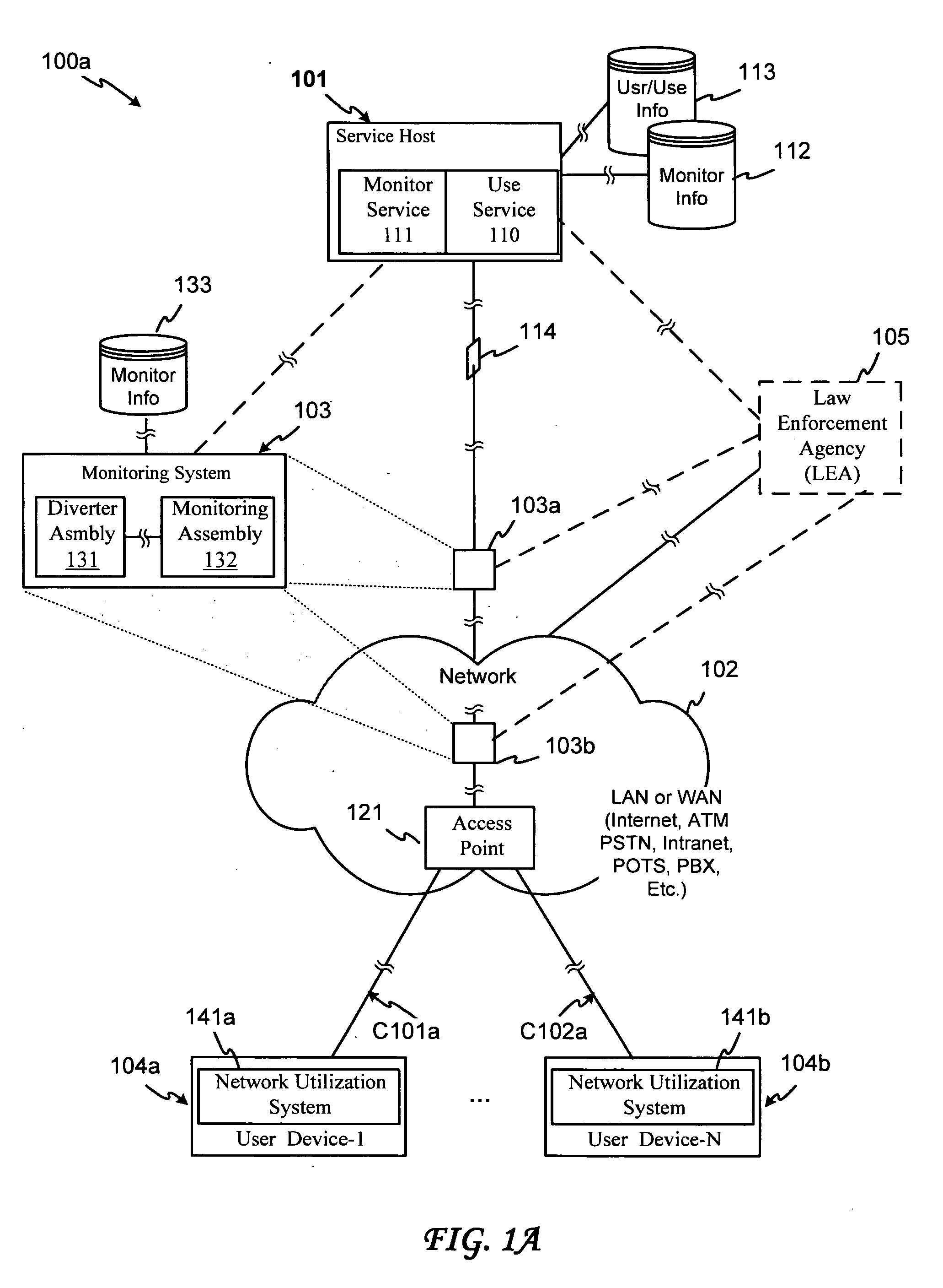
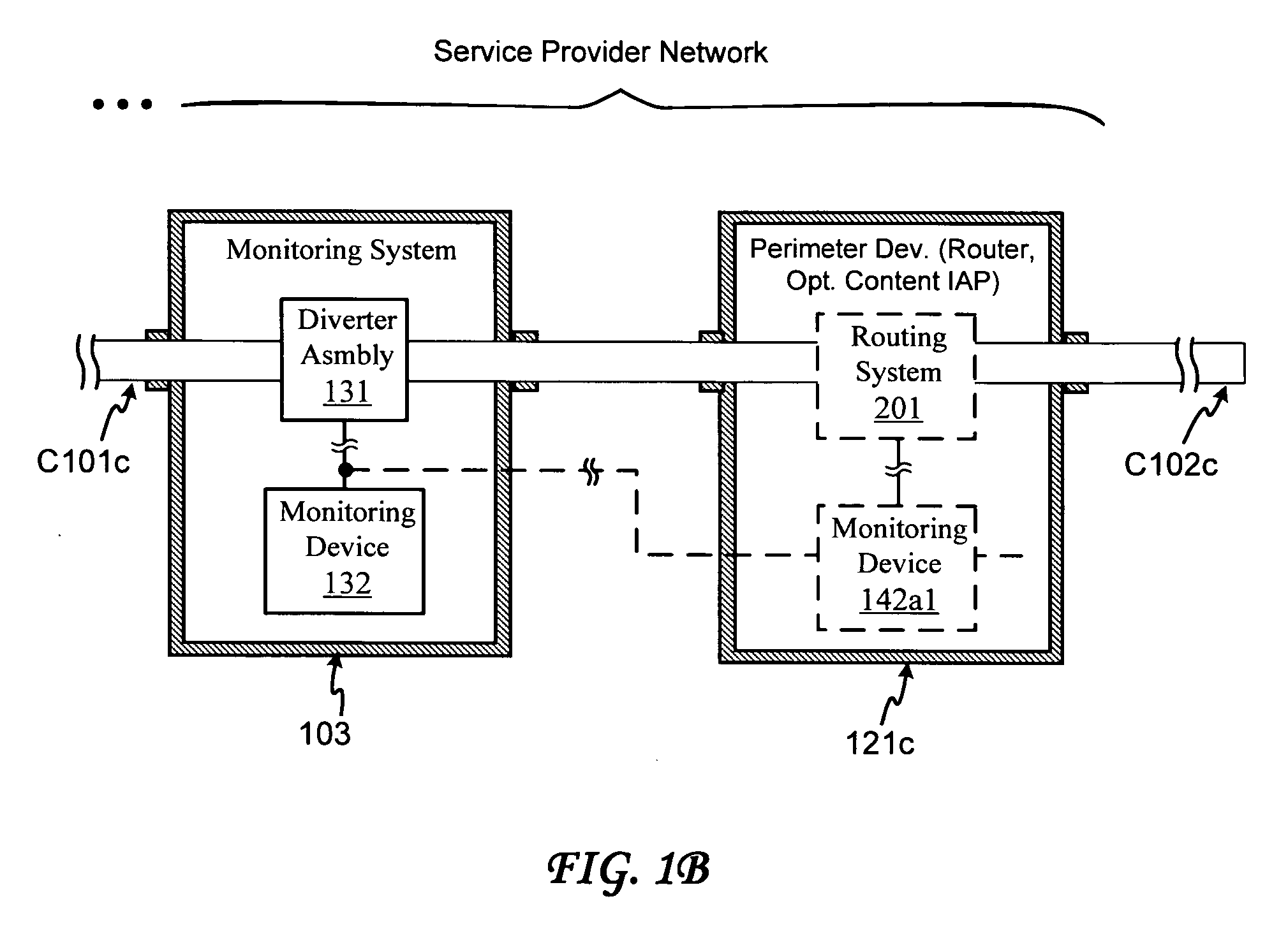
An optical network monitoring system and method provide for optical network diverting or further legal intercept, operational and / or other monitoring of general or specific transmission information that may be transmitted via a network optical branch. In one embodiment, a splitter within a diverter assembly diverts a portion of a received transmission signal (strength) to an optical receiver or re-transmitter, and outputs a further portion of the signal via a diverter assembly output or further via a re-transmitter or booster. In another embodiment, the splitter is generally matched to the receiver. A further embodiment provides for transferring the diverted portion to a monitoring assembly with which the diverting assembly may be matched, disposed or otherwise integrated, and which may provide for configuring the diverting assembly. The monitoring assembly may further provide for conducting monitoring processing, which may include receiving additional information from a service host or other system component, processing the diverted portion, additional information or both, and / or using the additional information for processing the diverted portion. The monitoring assembly may still further receive a monitoring request from a monitoring requester or other authorization authority that may include monitoring processing criteria, and may transfer designated content to a designated receiver.

Description

BACKGROUND OF THE INVENTION [0001] 1. Field of Invention [0002] The present invention relates in general to the field of computer networks and more specifically to computer networks including optical communication couplings. [0003] 2. Description of the Background Art [0004] Optical communication links continue to present an attractive network communication coupling option within a network system—especially for relatively high speed and low cost point-to-point connections. However, monitoring such optical networks may become particularly problematic in view of recent developments. [0005] Traditionally, network monitoring has encompassed verification or analysis of network operations, such as throughput, error rate, and so on. As with wire networks, such monitoring of optical networks is typically conducted by simply tapping into electrically available user communication traffic at a service provider server. [0006] The World Trade Center bombing and other recent events are, however, ...

Claims


Application Information

Patent Timeline
IPC IPC(8): H04B10/00
CPCH04B10/079H04L63/20H04L43/0888
Inventor GREENSPAN, DANIEL
Owner CISCO TECH INC
Learn More