
Centrifuge with clutch mechanism for synchronous blade and bowl rotation

a clutch mechanism and centrifuge technology, applied in centrifuges and other directions, can solve the problems of clogging filter paper or cartridges, generating immense labor costs or waste streams that may be greater, and requiring disposal, so as to achieve the effect of reducing the entrainment of gas

Inactive Publication Date: 2006-11-23
BEATTEY JEFFERY N
View PDF81 Cites 0 Cited by
  • Summary
  • Abstract
  • Description
  • Claims
  • Application Information

AI Technical Summary

Benefits of technology

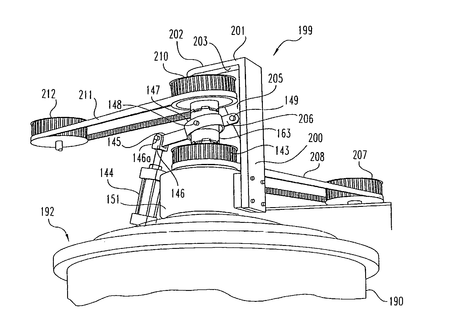
"The invention is a centrifuge with a spindle and a bowl that rotate together. The centrifuge has a drive shaft with scraper blades attached to it. The centrifuge also has a clutch mechanism that can engage or disengage the spindle and the scraper blades. The invention also includes a mechanism to selectively couple the drive shaft and spindle together, as well as a housing with a rotatable bowl and a tangential outlet to minimize gas entrainment during processing. The technical effects of the invention include improved solids removal efficiency, reduced gas entrainment, and improved processing control."

Problems solved by technology

Settling is a slow process and other alternatives generate an immense labor cost or a waste stream that may be greater than the solids alone.
Centrifugal separation is preferable to the more traditional medium of filtration because filtration does not allow for removal of submicron particles without extensive and very expensive filtering.
When such filtering is performed, the filter paper or cartridges become clogged quickly and must be disposed of.
Additionally, these filtration devices often cannot pass high viscosity fluid.
For example, metal working coolants often become contaminated during grinding, wire drawing, machining, polishing, vibratory deburring or other metal working processes.
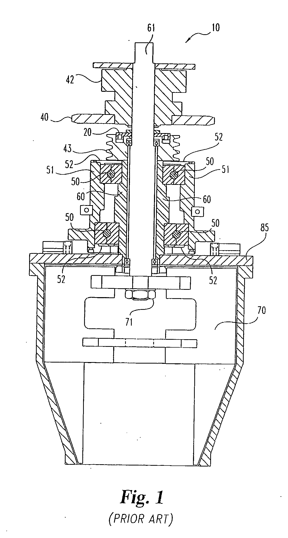
This frictional mechanism does not provide the consistent synchronous blade and bowl rotation desired.
Since the frictional mechanism does not provide a positive lock between the bowl and the blade there is no way of knowing whether the bowl and blade are continuing to rotate together during processing.
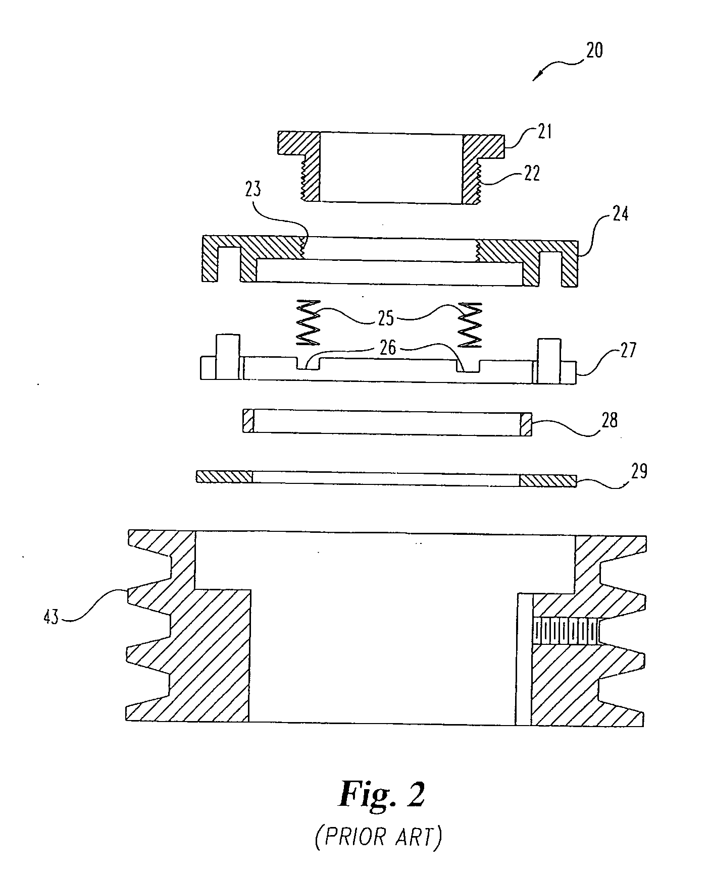
Furthermore, the frictional clutch mechanism possesses a great many parts, which increases the amount of time that must be spent for maintenance purposes.
Additionally, current systems are prone to spray or mist the fluids exiting the rotating bowl, which can be hazardous to human occupants in the room where centrifugation is occurring.
Also, this spray or mist can collect and cause dripping which coats the centrifuge or surrounding machinery, and may contaminate the solids expelled from the centrifuge into a waiting receptacle.
Another difficulty encountered is that some sticky solids refuse to let go of the blade during scraping.
However, each blade must be balanced to reduce vibration of the system, and it is expensive to produce and balance each blade properly.

Method used


Image

  • Centrifuge with clutch mechanism for synchronous blade and bowl rotation
  • Centrifuge with clutch mechanism for synchronous blade and bowl rotation
  • Centrifuge with clutch mechanism for synchronous blade and bowl rotation

Examples


Embodiment Construction

[0032] For the purposes of promoting an understanding of the principles of the invention, reference will now be made to the embodiments illustrated in the drawings and specific language will be used to describe the same. It will nevertheless be understood that no limitation of the scope of the invention is thereby intended, any alterations and further modifications in the illustrated device, and any further applications of the principles of the invention as illustrated therein being contemplated as would normally occur to one skilled in the art to which the invention relates.

[0033] In order to more fully illustrate the advantages of the present invention, the device of the prior art will be described. With reference to FIGS. 1 and 2, a prior art centrifugal separator with a frictional mechanism to ensure synchronous bowl and blade rotation is illustrated. A portion of the prior art assembly 10 is shown in FIG. 1 with more detail of the frictional clutch assembly 20 shown in FIG. 2....


PUM


Abstract

An improved centrifuge apparatus comprising a spindle with an affixed bowl and a drive shaft passing through the spindle with a plurality of scraper blades affixed which rotate within the bowl. The spindle is driven by a pulley with a belt attached to a motor. The centrifuge has a clutch mechanism which provides a positive lock to insure synchronous blade and bowl rotation during processing. The clutch mechanism comprises a shifting coupling attached to the drive shaft with a bottom set of teeth and a top set of teeth. The bottom set of teeth interlockingly engage a matching set of teeth located on either the pulley or the top of the spindle. The top set of teeth interlockingly engage a matching set of teeth that are either immovably attached to a plate or attached to a sprocket which is rotatably attached to the plate. The scraper blades have recesses in their front face to allow a variable cutting edge geometry and the mixing and matching of cutting edge geometry while permitting the use of the same base blade. The centrifuge has a tangential outlet and an annular housing to minimize spray and misting in the exiting centrifuged liquid.

Description

CROSS-REFERENCE TO RELATED APPLICATIONS [0001] This application is a divisional of application Ser. No. 10 / 234,296, filed Sep. 3, 2002, pending, which is a continuation of application Ser. No. 09 / 090,043, filed Jun. 3, 1998, now U.S. Pat. No. 6,478,724.BACKGROUND OF THE INVENTION [0002] The present invention relates to a centrifugal separation device and method of separating solids in liquids. The liquid has solid particles in suspension. Suspended solids removal can be achieved in many ways. Solids can be settled out in a tank, filtered out using cartridges or indexing paper or a filter press. Settling is a slow process and other alternatives generate an immense labor cost or a waste stream that may be greater than the solids alone. [0003] Use of a centrifugal separation device allows the extraction of the solid particles from the liquid. In a centrifugal separator, the separation of the solid from the liquid is commonly accomplished by pumping the contaminated liquid or coolant in...

Claims


Application Information

Patent Timeline
Patent Type & Authority Applications(United States)
IPC IPC(8): B04B11/08B04B9/08B04B11/04
CPCB04B9/08B04B2011/086B04B11/08B04B11/043
Inventor BEATTEY, JEFFERY N.
Owner BEATTEY JEFFERY N
Learn More