
Reinforced high strength microwave antenna

Inactive Publication Date: 2006-11-16
TYCO HEALTHCARE GRP LP
View PDF99 Cites 117 Cited by
  • Summary
  • Abstract
  • Description
  • Claims
  • Application Information

AI Technical Summary

Benefits of technology

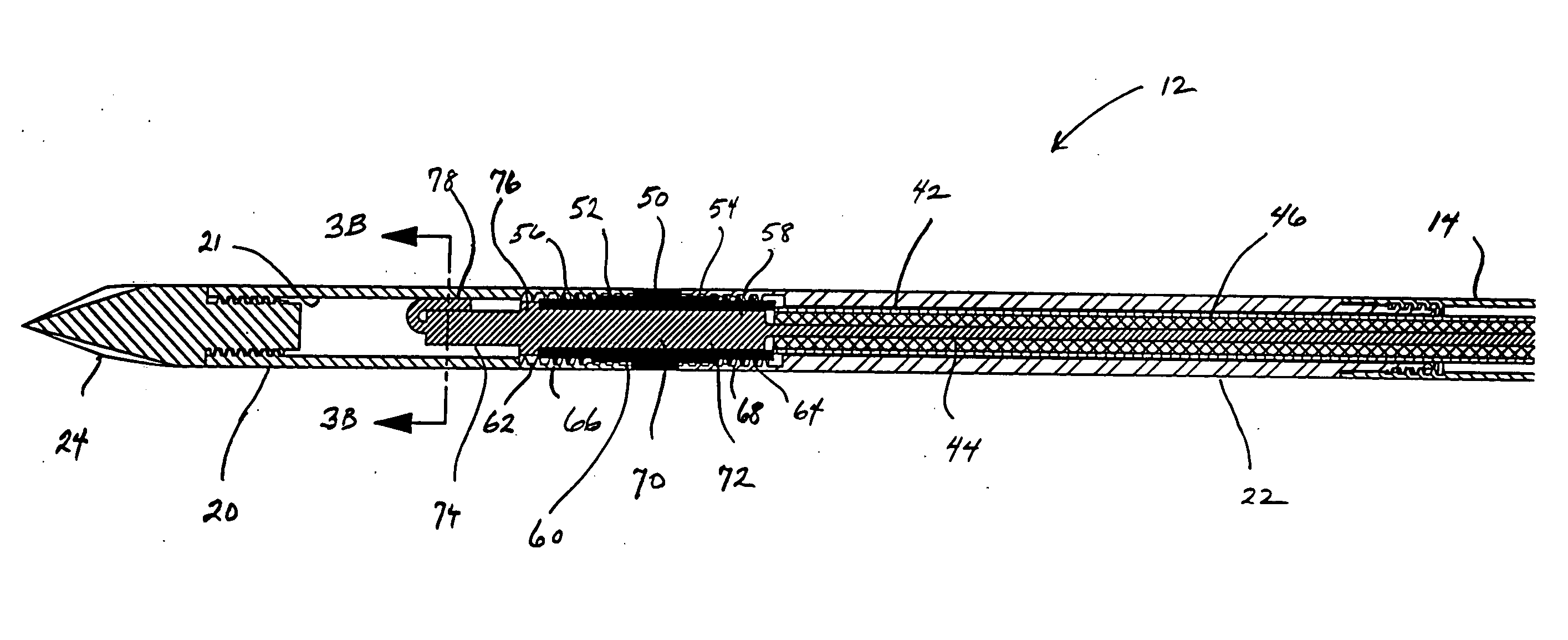
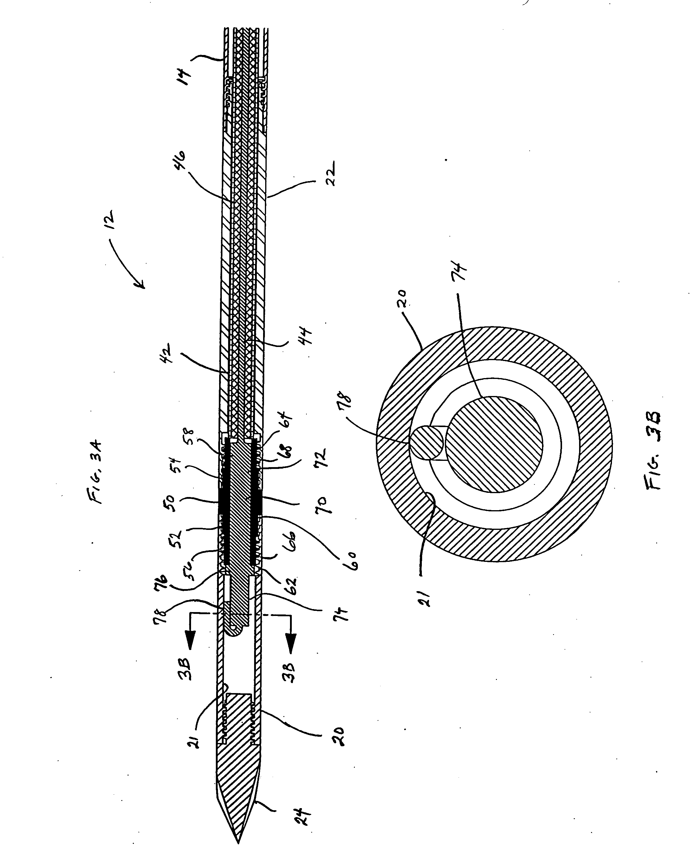
[0013] To improve the energy focus of the antenna assembly, an electrical choke may also be used in any of the variations described herein to contain returning currents to the distal end of the antenna assembly. The choke may be disposed on top of a dielectric material on the antenna proximal of the radiating section. The choke is preferably comprised of a conductive layer and may be further covered by a tubing or coating to force the conductive layer to conform to the underlying antenna.
[0014] Additionally, variations on the choke, the tubing or coating, any sealant layers, as well as other layers that may be disposed over the antenna assembly may be used. Certain layers, e.g., a heatshrink layer disposed over the antenna assembly, may have wires or strands integrated within the layer to further strengthen the antenna assembly. Kevlar wires, for instance, may be integrally formed into the layer and oriented longitudinally with the antenna axis to provide additional strength.

Problems solved by technology

However, this non-invasive procedure may result in the unwanted heating of healthy tissue.
Thus, the non-invasive use of microwave energy requires a great deal of control.
However, at slightly elevated temperatures above the approximate range of 43° C. to 45° C., thermal damage to most types of normal cells is routinely observed.
However, many types of malignancies are difficult to reach and treat using non-invasive techniques or by using invasive antenna probes designed to be inserted into a normal body orifice, i.e., an easily accessible body opening.
These types of conventional probes may be more flexible and may also avoid the need to separately sterilize the probe; however, they are structurally weak and typically require the use of an introducer or catheter to gain access to within the body.
Moreover, the addition of introducers and catheters necessarily increase the diameter of the incision or access opening into the body thereby making the use of such probes more invasive and further increasing the probability of any complications that may arise.
However, such rigid, needle-like probes may experience difficulties in failing to provide uniform patterns of radiated energy; and may fail to provide uniform heating axially along and radially around an effective length of the probe.
Accordingly, it may be difficult to otherwise control and direct the heating pattern when using such probes.

Method used


Image

  • Reinforced high strength microwave antenna
  • Reinforced high strength microwave antenna
  • Reinforced high strength microwave antenna

Examples


Embodiment Construction

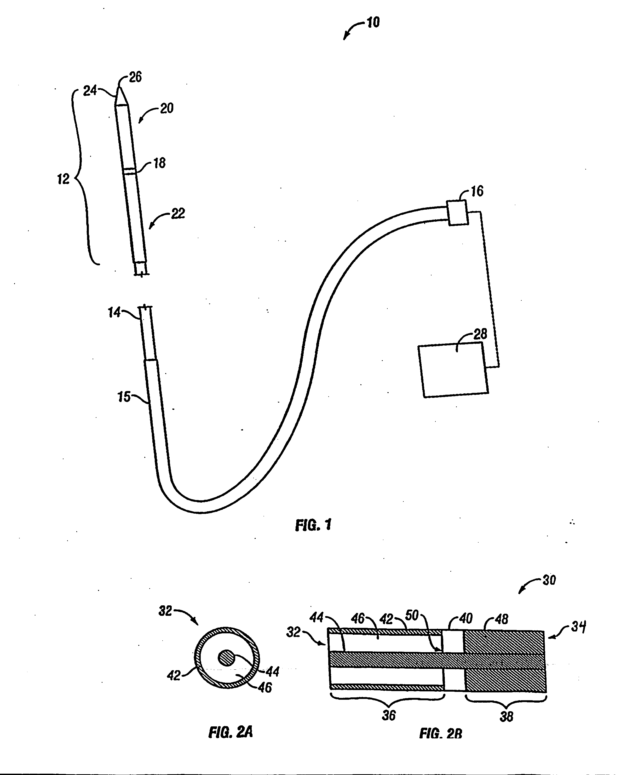
[0025] During invasive treatment of diseased areas of tissue in a patient, trauma may be caused to the patient resulting in pain and other complications. Various microwave antenna assemblies, as described herein, are less traumatic than devices currently available and as described in further detail below, methods of manufacturing such devices are also described. Generally, the devices and assemblies described here allow for the direct insertion of a microwave antenna into tissue for the purposes of diagnosis and treatment of disease. FIG. 1 shows a representative diagram of a variation of a microwave antenna assembly 10. The antenna assembly 10 is generally comprised of radiating portion 12 that may be connected by shaft 14 via cable 15 to connector 16, which may further connect the assembly 10 to a power generating source 28, e.g., a generator or source of microwave energy. Assembly 10, as shown, is a dipole microwave antenna assembly, but other antenna assemblies, e.g., monopole h...


PUM


Abstract

High-strength microwave antenna assemblies and methods of use are described herein. The microwave antenna has a radiating portion connected by a feedline to a power generating source, e.g., a generator. Proximal and distal radiating portions of the antenna assembly are separated by a junction member. A reinforcing member is disposed within the junction member to increase structural rigidity.

Description

FIELD [0001] The described devices relate generally to microwave antenna probes and methods of their use, e.g., in tissue ablation applications. More particularly, the described devices relate to microwave antennas that may be inserted directly into tissue for diagnosis and treatment of diseases. BACKGROUND [0002] In the treatment of diseases such as cancer, certain types of cancer cells have been found to denature at elevated temperatures (which are slightly lower than temperatures normally injurious to healthy cells). These types of treatments, known generally as hyperthermia therapy, typically utilize electromagnetic radiation to heat diseased cells to temperatures above 41° C. while maintaining adjacent healthy cells at lower temperatures where irreversible cell destruction will not occur. Other procedures utilizing electromagnetic radiation to heat tissue also include ablation and coagulation of the tissue. Such microwave ablation procedures, e.g., such as those performed for m...

Claims


Application Information

Patent Timeline
IPC IPC(8): A61B18/18A61N1/00
CPCA61B18/18H01Q9/22A61B18/1815A61B2018/00797A61B2018/00821A61B2018/1892A61B2018/00011A61B2018/00577A61B2018/00589A61B2018/1838A61B2018/1853A61B2018/00642A61B2018/00702A61B2018/00791A61B2018/1846
Inventor TUROVSKIY, ROMANSU, TEDPRAKASH, MANIKIM, STEVEN
Owner TYCO HEALTHCARE GRP LP
Learn More