Sheet feeding unit for continuous form recording medium

a continuous form and feeding unit technology, applied in the direction of electrographic process apparatus, instruments, optics, etc., can solve the problems of requiring additional space in the image forming apparatus, image may not be formed in the correct position of the roll sheet paper,

Inactive Publication Date: 2006-11-16
ASAHI KOGAKU KOGYO KK
View PDF8 Cites 4 Cited by
  • Summary
  • Abstract
  • Description
  • Claims
  • Application Information

AI Technical Summary

Benefits of technology

[0006] In view of the foregoing shortcomings, the present invention is advantageous in that a feeding unit of a continuous form recording medium is provided, and particularly to a feeding unit wi...

Problems solved by technology

Therefore, the roll sheet paper may be displaced from a correct position with respect to the image forming apparatus, and when image forming is resumed in the same image forming apparatus, the image may not be formed in a correct position of the roll sheet paper.
Such a locking mechanism with an electromagnetic clutch may be also employed in the image forming appa...

Method used


Image

  • Sheet feeding unit for continuous form recording medium
  • Sheet feeding unit for continuous form recording medium
  • Sheet feeding unit for continuous form recording medium

Examples


first embodiment

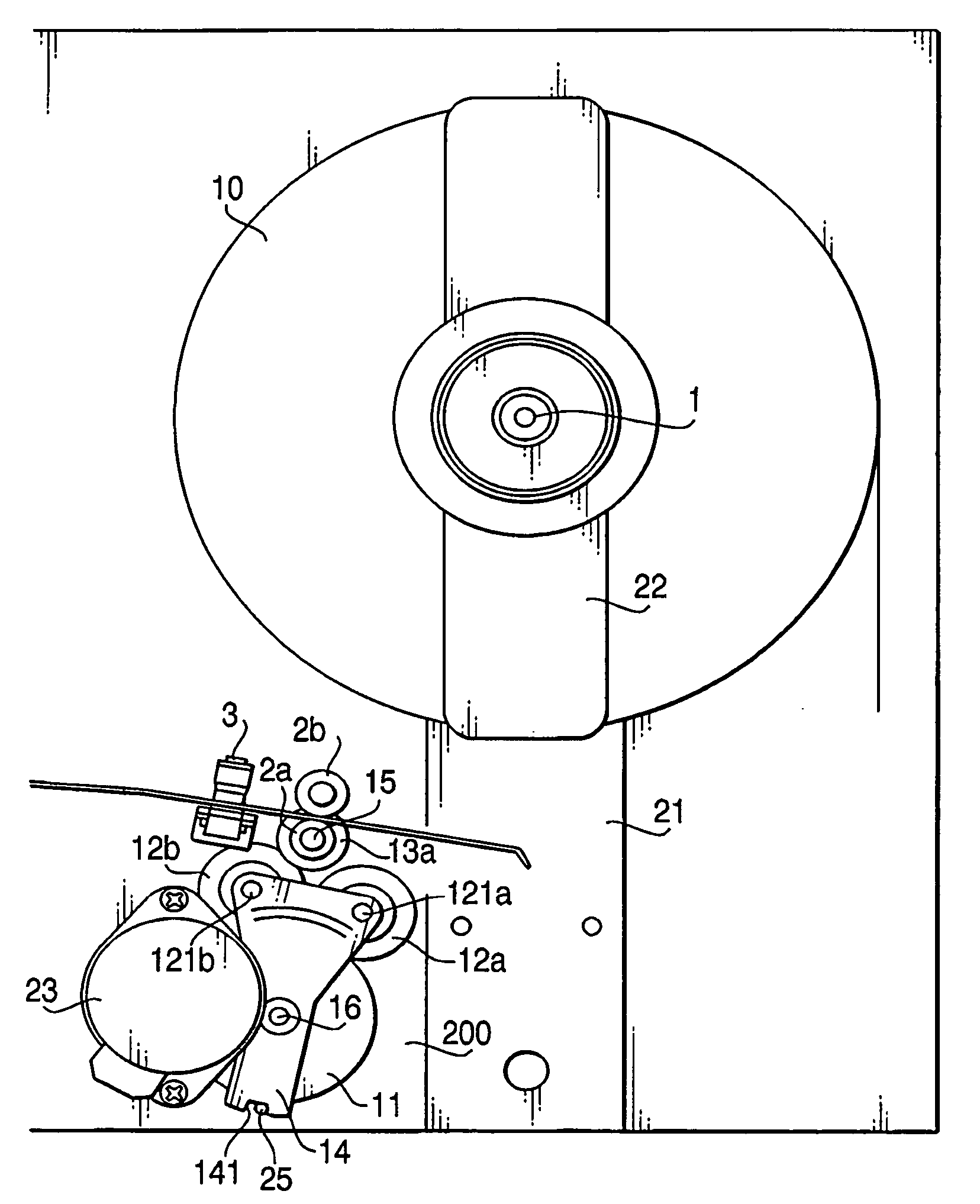
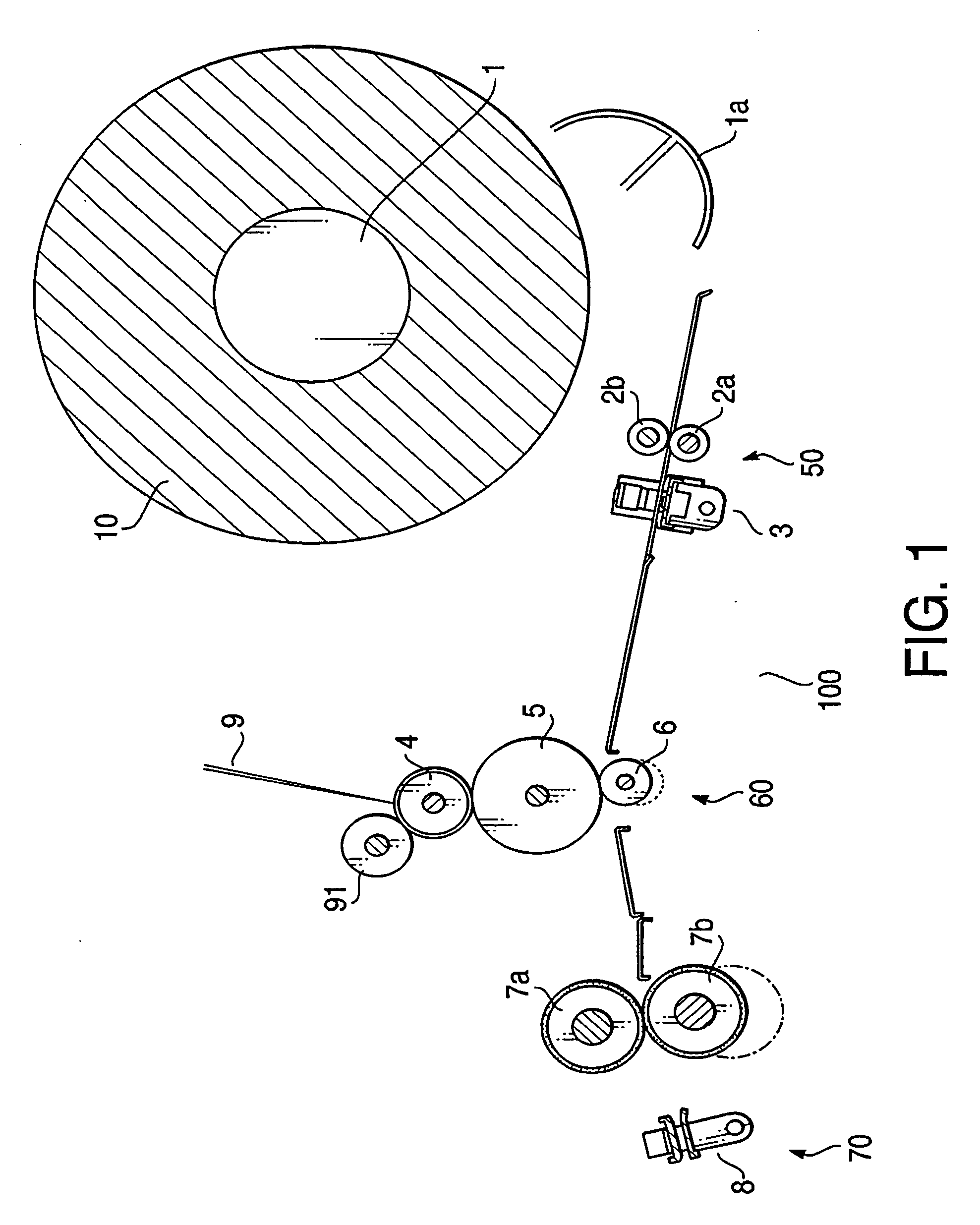
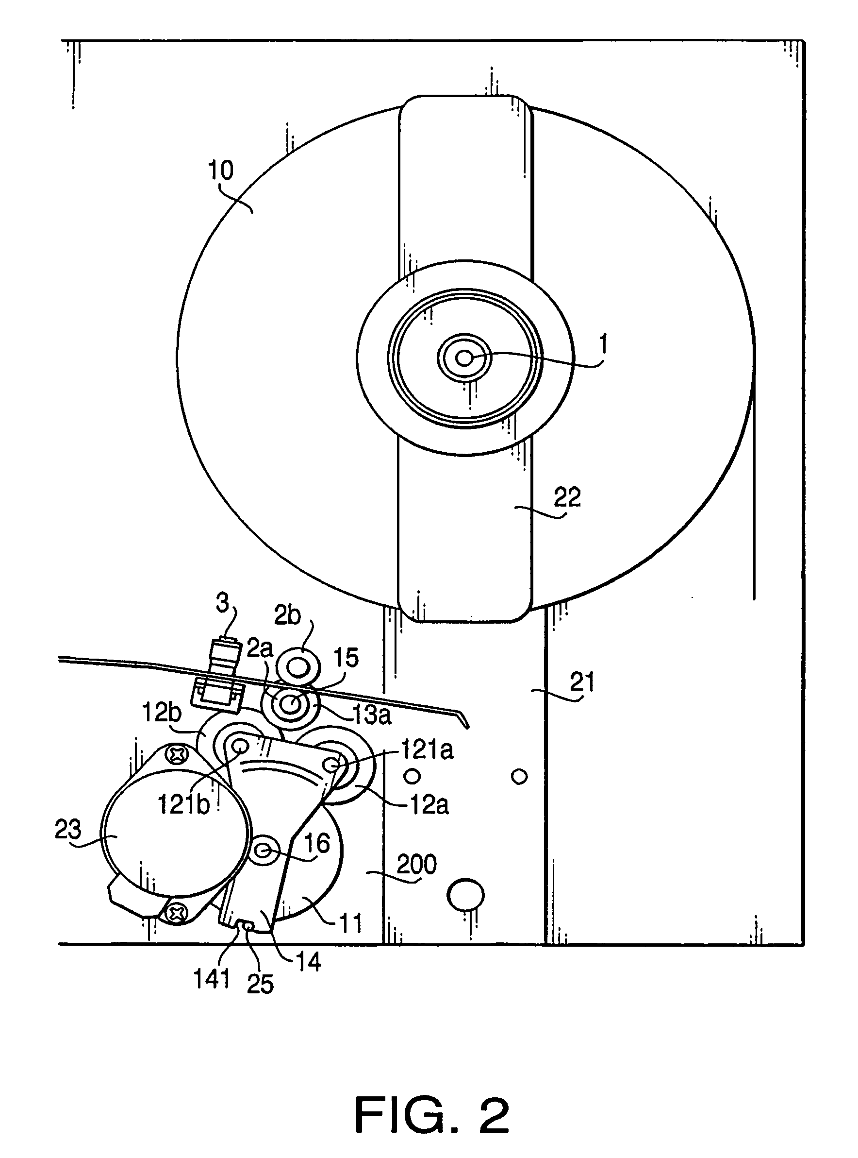
[0033] Referring to the accompanying drawings, a feeding unit with a drive direction switching system for a continuous form recording medium according to an embodiment of the present invention will be described in detail. FIG. 1 is a diagram to illustrate a general configuration of the image forming apparatus 100 according to the present invention. FIG. 2 is a diagram to illustrate a drive direction switching system according to the embodiment of the present invention. The image forming apparatus 100, which is often used as an output device for a computer, is adapted to form an image on a continuous form recording sheet (hereinafter referred to as a recording sheet) 10 in an electrophotographic method by exposing a surface of a photoconductive drum 4 to a laser beam modulated according to information (image data) inputted by a user.

[0034] As shown in FIGS. 1 and 2, the image forming apparatus 100 is provided with a feeding unit 50 including a core roll 1, around which the recording ...

second embodiment

[0061] Hereinafter, referring to FIGS. 7-10, a drive direction switching system 300, which is replaceable with the drive direction switching system 200 in the feeding unit 50 of the image forming apparatus 100, will be described. It should be noted that in FIGS. 7-10, gears 311a, 311b, 312a, 312b, 313, 24 are represented in disks, and cog tips of each gear correspond to an circumference of each disk. In the present embodiment, configurations corresponding to the configuration of the previous embodiment are referred to by the identical reference numerals, and description of those is omitted.

[0062]FIG. 7 is an enlarged perspective view of the drive direction switching system 300 according to a second embodiment of the present invention. FIG. 8 is an enlarged perspective view of the drive direction switching system 300 taken from an opposite side of the side shown in FIG. 7 according to the second embodiment of the present invention. FIG. 9 is a cross-sectional partial view of the driv...


PUM


Abstract

A feeding unit for a continuous form recording medium, having a feed roller, a drive motor, a first transmitting system, a second transmitting system, is provided. The first transmitting system is adapted to transmit rotating force from the drive motor to the feed roller so that the feed roller is rotated in a normal feeding direction to carry the continuous form recording medium and to allow the feed roller to be rotated in the normal feeding direction by external force. The second transmitting system is adapted to transmit the rotating force from the drive motor to the feed roller so that the feed roller is rotated in a reverse feeding direction. The switching system transmits stalling torque of the drive motor to the feed roller associated by the second transmitting system before and after the continuous form recording medium is processed through an image forming operation.

Description

BACKGROUND OF THE INVENTION [0001] The present invention relates to an image forming apparatus capable of forming an image on a continuous form recording sheet in an electrophotographic method, and particularly to a sheet feeding unit for a continuous form recording sheet, which is used in the image forming apparatus, capable of restricting a movement of the recording sheet in a standby period of the image forming apparatus. [0002] Conventionally, an image forming apparatus employing an electrophotographic technology, such as a copier and a laser beam printer, is known. Such an image forming apparatus is adapted to form a latent image corresponding to image data on a surface of a photoconductive drum by laser beam or the like. When toner is adhered to the latent image, a toner image is formed on the surface of the photoconductive drum. The toner image is then in a developing unit transferred to a surface of a recording sheet that has been introduced via a sheet feed roller of a shee...

Claims


Application Information

Patent Timeline
IPC IPC(8): G03G15/00
CPCG03G15/652
Inventor TAKANO, MASATOSHI
Owner ASAHI KOGAKU KOGYO KK
Why Eureka
Try Eureka